


Maximum Power Transfer Theorem Explained: Design, Examples, and Common Misconceptions
The Maximum Power Transfer Theorem is a cornerstone of electrical engineering that informs how designers deliver optimal power to a load. In practice, the greatest power dissipation occurs when the load resistance equals the Thevenin or Norton resistance of the source network.
In radio transmitter design, this principle manifests as impedance matching: the antenna or transmission line’s impedance is matched to the final power amplifier’s impedance to maximize radio‑frequency power output. Impedance, which represents the overall opposition to AC and DC current, behaves much like resistance; equal source and load impedances guarantee the most efficient power transfer. A load impedance that is too high under‑delivers power, while a load that is too low not only reduces output but can also cause overheating of the amplifier’s internal Thevenin or Norton resistance.
When a load resistance deviates from the source’s equivalent resistance—whether higher or lower—the power dissipated in the load falls below its maximum. This is a key consideration in any application where maximizing load power is critical.
Maximum Power Transfer Example
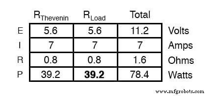
Using the Thevenin equivalent circuit, the theorem dictates that the load resistance providing maximum power dissipation is equal to the Thevenin resistance (0.8 Ω in this case). With this optimal load, the power dissipated is 39.2 W.
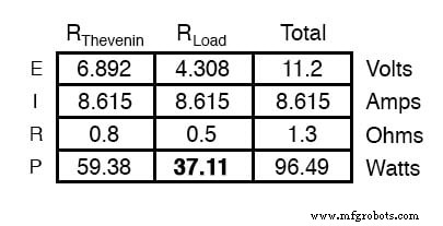
If the load resistance is lowered to 0.5 Ω, the power dissipated in the load decreases, even though the total circuit power increases. The accompanying image illustrates this effect.
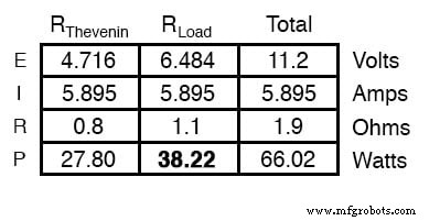
Similarly, increasing the load resistance to 1.1 Ω also reduces load power, as shown below.
When designing for maximum load power, reduce the network to its Thevenin (or Norton) equivalent and set the load resistance equal to that value. This approach is widely applied in radio transmitter final‑amplifier design, grid‑tied inverter loading of solar arrays, and electric‑vehicle motor power delivery.
Maximum Power Doesn’t Mean Maximum Efficiency
It is important to note that the Maximum Power Transfer Theorem is not synonymous with maximum efficiency. In AC power distribution, the goal is high efficiency, which typically requires the source impedance to be much lower than the load impedance. High‑fidelity audio amplifiers adopt a similar strategy, employing a low output impedance and a high speaker load impedance to achieve a damping factor of 100–1,000.
Moreover, achieving the lowest possible noise—such as in a low‑level RF amplifier feeding a receiver—often necessitates a deliberate impedance mismatch, contrary to the theorem’s recommendation.
Review:
- The Maximum Power Transfer Theorem states that a load dissipates maximum power when its resistance equals the source’s Thevenin or Norton resistance.
- It does not guarantee maximum efficiency.
Related Worksheet:
- Thevenin’s, Norton’s, and Maximum Power Transfer Theorems Worksheet
Industrial Technology
- Understanding AC Circuits: A Beginner's Guide
- Power Sources: AC and DC Explained
- Protective Relays: Safeguarding Industrial Power Systems
- Amplifiers: Harnessing Active Devices to Boost Power
- Understanding Bels and Decibels: From Power Gain to Voltage Conversion
- Comprehensive Guide to Diode Ratings & Datasheet Parameters
- Rectifier Circuits: From Half‑Wave to Polyphase Full‑Wave Designs
- Calculating Power Dissipation in Resistive Circuits
- Wireless Power Transfer: Fundamentals and Benefits
- Comprehensive Guide to Conveyor Types Used in Thermal Power Plants