


AC Bridge Circuits: Precise Impedance Measurement with Balanced Ratios
Just as DC bridge circuits enable accurate resistance measurement, AC bridge circuits extend this principle to determine unknown impedances—resistive, capacitive, and inductive—using balanced voltage dividers and a sensitive null detector.
How Does a Bridge Circuit Work?
A bridge circuit consists of two parallel voltage dividers fed by the same source voltage. A null‑detector meter is connected across the dividers; when the bridge is balanced, the detector reads zero volts, indicating a null condition.
A balanced bridge shows a “null,” or minimum reading, on the indicator.
Any of the four resistors can serve as the unknown component; its value is deduced from the ratio of the three calibrated resistors. When balanced, the bridge satisfies the equation:
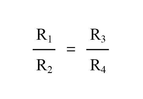
One advantage of using a bridge for resistance measurement is that the source voltage does not influence the result. A higher supply voltage improves the sensitivity of the null detector, allowing finer imbalance detection, but it does not introduce systematic error.
Impedance Bridge
Impedance bridges operate on the same principle; however, the balance equation involves complex quantities, requiring equal magnitude and phase across the bridge arms for a null reading. The null detector must be capable of detecting very small AC voltages—oscilloscopes, sensitive electromechanical meters, or headphones (within the audio range) are common choices.
Null Detector for AC
Audio headphones can serve as an effective null detector when paired with an impedance‑matching transformer. Headphones typically present low impedance (≈8 Ω), so a step‑down transformer aligns the low‑current signal to the headphone’s impedance, enhancing sensitivity.
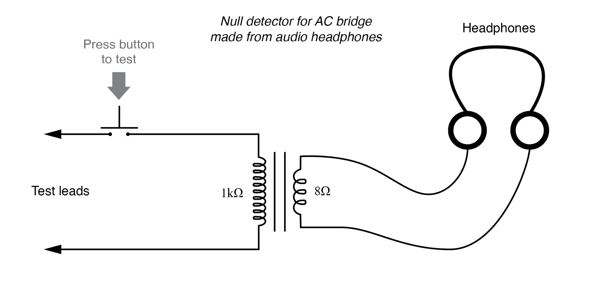
Using a closed‑cup headphone pair, currents below 0.1 µA can be detected with this simple circuit. The same performance is achievable with a 120/6 V power transformer or a 1000:8 Ω audio transformer. A push‑button switch allows the detector to respond to signals from DC up to over 2 MHz; a “click” is audible with each actuation.
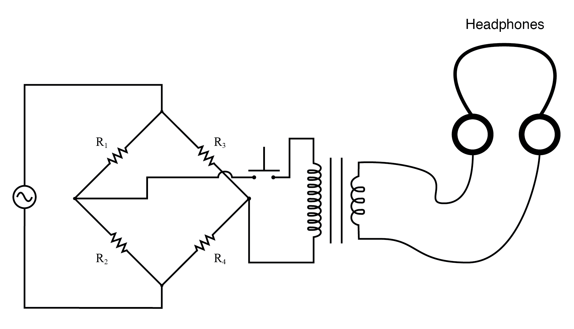
When the bridge is adjusted, a balanced state is reached when the headphones cease to produce clicks or tones during the switch operation.
General AC Impedance Bridge
For arbitrary complex impedances, the bridge legs are represented as boxes with impedance Z. Balance requires equal impedance ratios on opposite sides:
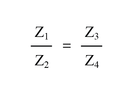
Both magnitude and phase must match; otherwise a residual voltage persists across the null detector.
Versatile Bridge Configurations
Bridge circuits can measure virtually any electrical parameter—capacitance, inductance, resistance, or quality factor—by balancing an unknown against a known standard. Depending on the configuration, the unknown value may be read directly from a calibrated setting or calculated via a mathematical relationship.
Examples of Simple Bridges
The following symmetrical bridges illustrate the basic concept. In each case, a calibrated reactive component (inductor or capacitor) is adjusted until the bridge balances.
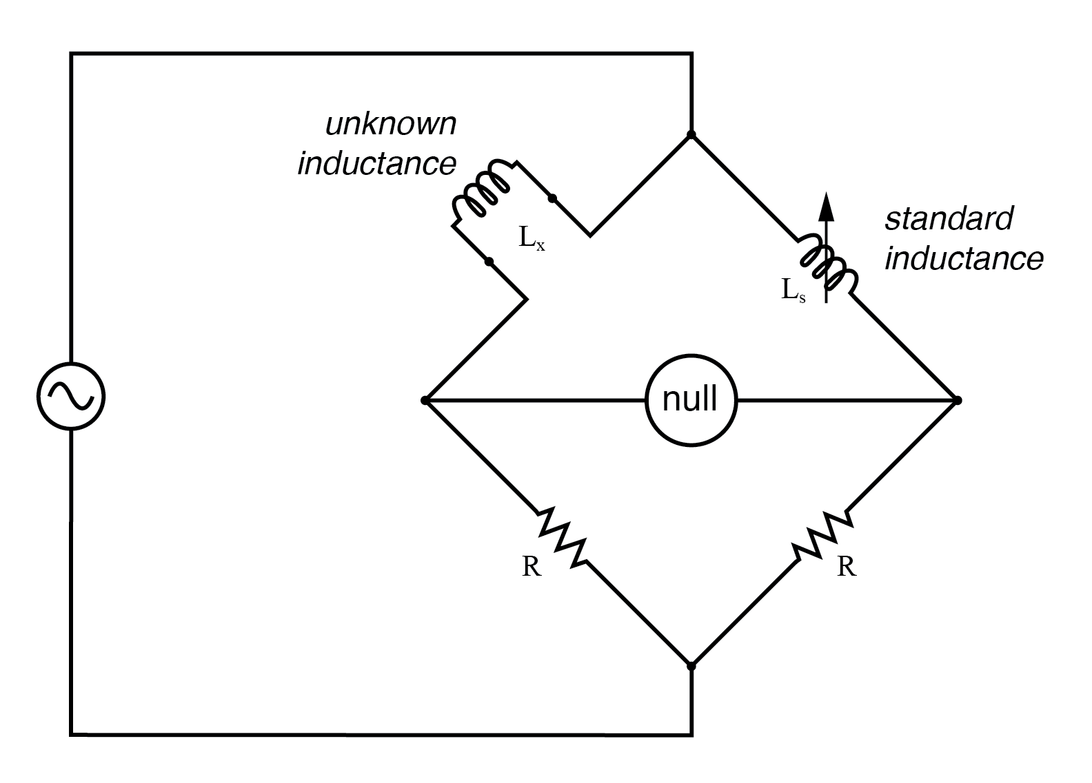
Symmetrical bridge for measuring an unknown inductor.
Symmetrical bridge for measuring an unknown capacitor.
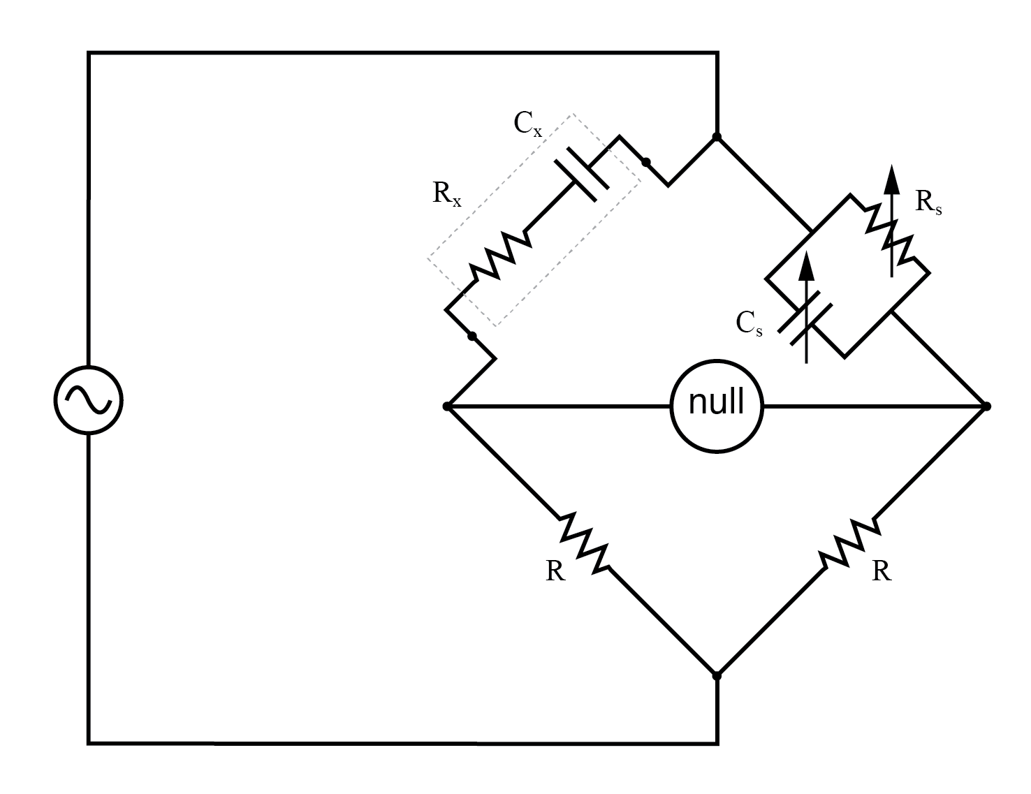
Wien Bridge
The Wien bridge introduces a parallel resistor‑capacitor standard to counteract the inherent resistance of real capacitors. This configuration balances an unknown series RC combination, enabling simultaneous measurement of capacitance and loss resistance.
By adjusting the standard resistor (Rs) and capacitor (Cs), the bridge achieves balance, and the unknown capacitance (Cx) and resistance (Rx) are derived from the measured settings.
Maxwell‑Wein Bridge
The Maxwell‑Wein bridge (often called the Maxwell bridge) measures inductance using a calibrated resistor and capacitor pair. Since inductive and capacitive phase shifts are opposite, the capacitor can counterbalance the inductor’s impedance in a symmetrical layout, eliminating errors due to mutual inductance.
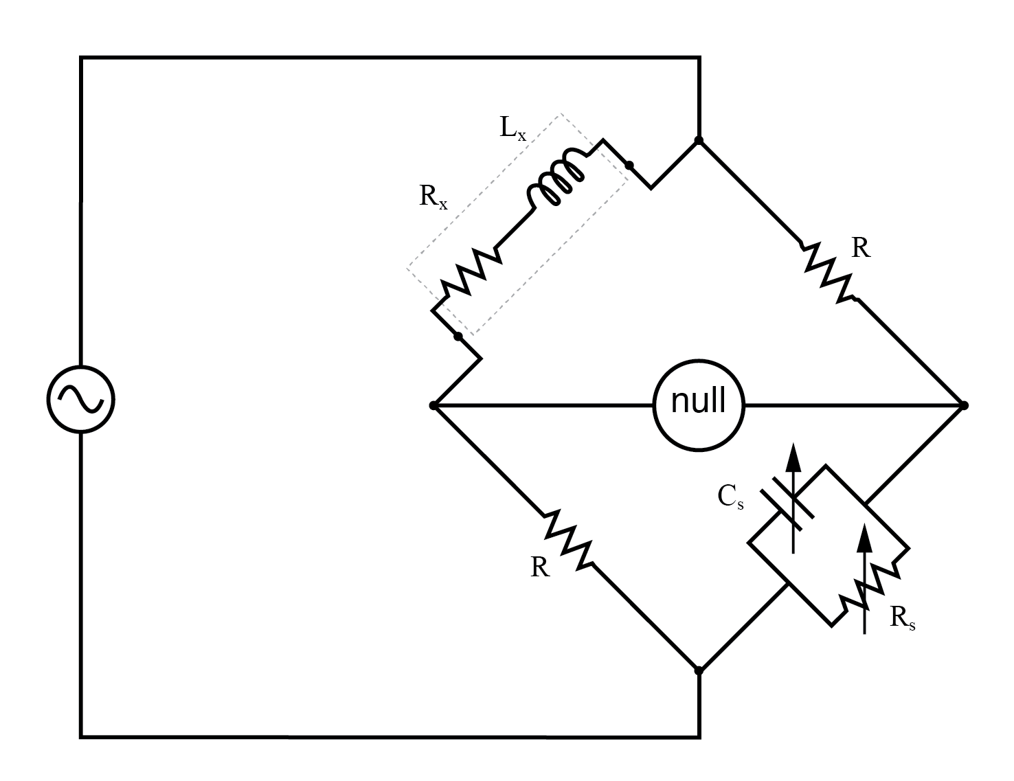
With a variable standard capacitor (Cs) and parallel resistor (Rs), the bridge balances at a frequency‑independent point, allowing accurate inductance measurement even under mixed‑frequency conditions.
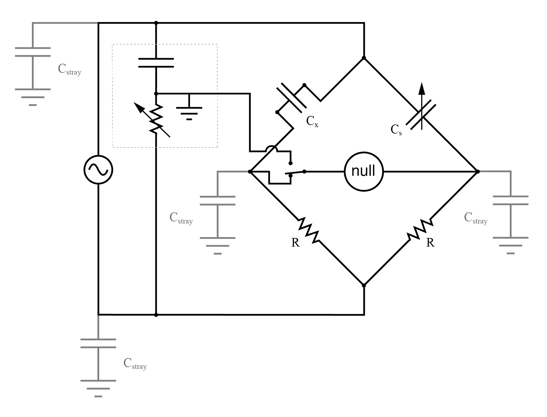
Addressing Stray Capacitance
Stray capacitance between the null detector and ground can introduce measurement errors. This is especially problematic if one side of the AC supply is grounded, as the leakage path is reduced and stray currents increase.
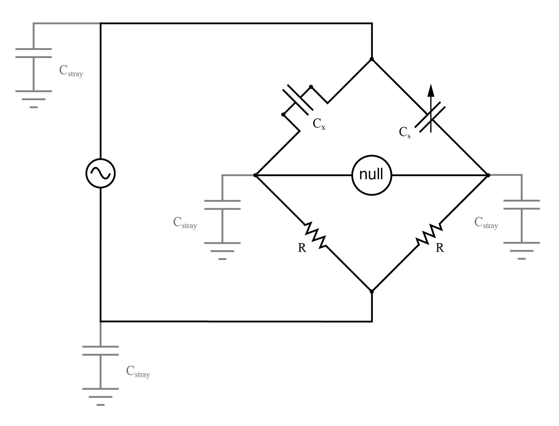
To mitigate this, the Wagner ground (or Wagner earth) is employed. It is a voltage divider that places the null detector at virtual ground without a direct connection, thereby eliminating leakage currents.
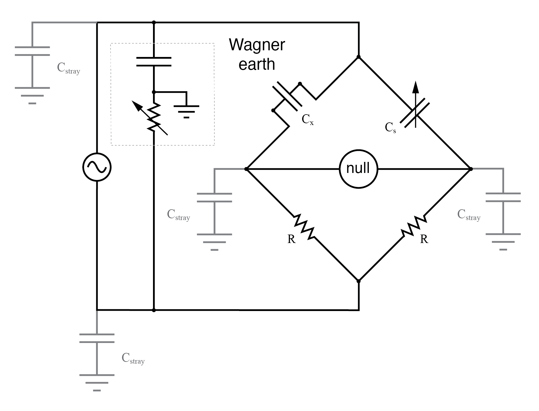
A two‑position switch allows verification of the Wagner ground by comparing the null detector’s reading in both bridge and Wagner configurations; zero in both confirms proper grounding.
Key Takeaways
- AC bridge circuits operate on the same principle as DC bridges but require equal complex impedance ratios for balance.
- Null detectors for AC bridges can be oscilloscopes, electromechanical meters, or headphones with impedance matching.
- Balanced bridges may involve multiple adjustments to match both magnitude and phase.
- Frequency‑sensitive bridges serve as accurate frequency meters when component values are known.
- The Wagner earth technique reduces stray‑capacitance errors by maintaining the null detector at virtual ground.
Related Worksheets
- AC Network Analysis Worksheet
Industrial Technology
- Foundations of DC Circuits: Understanding Direct Current and Core Electrical Concepts
- Understanding AC Circuits: A Beginner's Guide
- Full-Wave Bridge Rectifier: Design, Benefits, and Practical Implementation
- Rectifier Circuits: From Half‑Wave to Polyphase Full‑Wave Designs
- Understanding Clipper Circuits: Theory, Simulation, and Practical Applications
- Clamper Circuits – DC Restorers for Composite Video
- Crystal and Transistor Radio Circuits: From Basic Detectors to Integrated AM/FM Receivers
- Analog vs. Digital Computational Circuits: A Practical Guide
- Control Circuits: Fundamentals, Applications, and Best Practices
- Bridge Circuits: Wheatstone, Kelvin, and Their Role in Precise Electrical Measurements