


Advanced AC Position Transducers: From Potentiometers to Inductosyns & Capacitive Sensors
In modern automation, accurately converting mechanical motion into electrical signals is essential. While DC-based devices such as thermocouples and strain gauges have long served this purpose, AC transducers offer unique advantages—especially when contactless operation, high precision, and safety are paramount.
Potentiometer Basics
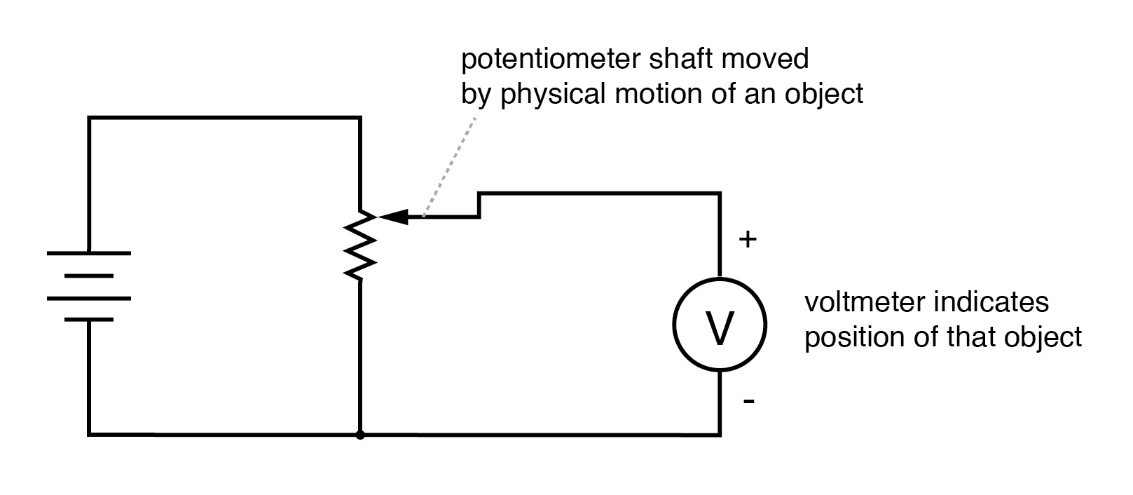
Potentiometer tap voltage indicates the position of a shaft‑mounted object.
Potentiometers provide a simple, low‑cost method for translating angular or linear displacement into a proportional voltage. However, they suffer from wear due to the sliding wiper, leading to drift, noise, and even the potential for arcing in hazardous environments. These limitations make them less suitable for demanding industrial or safety‑critical applications.
LVDT (Linear Variable Differential Transformer)
By replacing the sliding contact with a transformer core that moves freely between two secondary windings, the LVDT eliminates wear and eliminates arcing risk. It consists of a primary winding excited with AC and two secondary windings connected in series‑bucking fashion. As the core moves, the induced voltages in the two secondaries differ, and the output is their differential value.
Key attributes:
- Zero‑output when the core is centered.
- Output amplitude proportional to core displacement; phase indicates direction.
- Typical excitation: ≤10 V RMS, 50 Hz–20 kHz.
- Fast response requires higher excitation frequency; otherwise, rapid motion can distort the sine wave.
RVDT (Rotary Variable Differential Transformer)
Functionally similar to the LVDT, the RVDT measures angular displacement. The core revolves on a shaft, allowing measurement over a portion of 360° rather than a full revolution. This makes RVDTs ideal for rotary applications where contactless, high‑precision sensing is required.
Synchro / Selsyn
These devices adapt the transformer principle to full‑circle rotation. A wound‑rotor AC motor or generator structure is used, with a single AC‑excited primary winding on the rotor and a multi‑phase stator. The stator’s induced voltages vary with rotor angle, producing sine and cosine outputs that represent the shaft’s absolute position.
Synchros often operate in transmitter/receiver pairs, enabling remote position replication—an early example of this is the naval use of synchros to transmit rudder angles over long distances. Because the receiver’s rotor can be powered or left unpowered, the system can also function as an error detector.
Inductosyn (Linear Version of Resolver)
The Inductosyn replaces the circular stator with a fixed serpentine winding and a movable slider carrying two out‑of‑phase windings. As the slider traverses the serpentine, it produces sine and cosine waves that encode linear displacement. With a 100:1 transformer ratio, a few volts of AC excitation yields millivolt‑level outputs, which a resolver‑to‑digital converter (RDC) can digitize to 12‑bit resolution, achieving 25 µinches precision. A rotary Inductosyn can deliver sub‑arc‑second resolution with a 12‑bit RDC.
Capacitive Transducers
Capacitance varies with plate area, separation, and dielectric constant. By fixing two of these variables, a capacitive transducer can monitor the third with high sensitivity. Early work by H. Cremer (1907) used capacitive plates to detect cardiac activity; modern biomedical devices employ catheter‑based probes for real‑time monitoring of heart rhythms.
Capacitive transducers can be self‑contained: one plate is movable, varying either overlap area or separation distance; alternatively, a dielectric can be inserted or removed. Differential designs—using three wires instead of two—enhance immunity to external disturbances.
Differential Capacitive Transducer Bridge
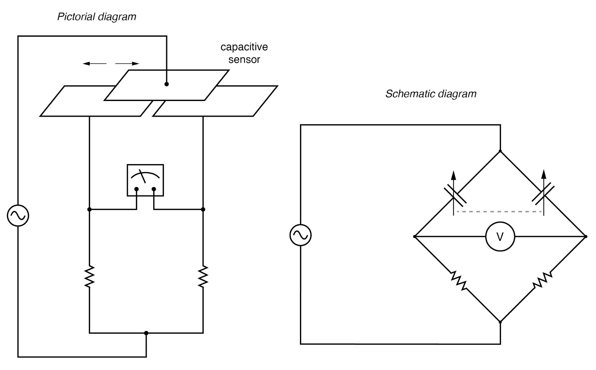
In a bridge configuration, the differential output is proportional to displacement, with phase indicating direction. Because capacitances are typically in the pico‑farad range, high‑frequency excitation (MHz) is used to reduce reactance, and careful shielding mitigates stray capacitance.
Differential Capacitive Transducer “Twin‑T”
Replacing the bridge with a twin‑T circuit simplifies the readout to a single DC voltage. Diodes charge two capacitors during alternating half‑cycles; the capacitor that holds charge longer generates a higher DC voltage. The load resistor then converts this difference into a DC output directly proportional to displacement.
Advantages include:
- Pure DC output—no need for phase analysis.
- Direct drive of electromechanical meters without amplification.
- All critical components ground‑referenced, reducing stray‑capacitance errors.
- Robustness to supply‑frequency variations and tolerant to mismatched diode drops.
A low‑pass filter can be added to suppress residual AC, yielding a clean DC signal for instrumentation.
Overall, AC transducers—from LVDTs and RVDTs to Synchros and Inductosyns, plus capacitive sensors—provide reliable, high‑accuracy, contactless position sensing for industrial automation, robotics, aerospace, and medical diagnostics.
Industrial Technology
- Exploring Voltage Addition with Series Battery Connections
- Voltage Divider Lab: Design, Measurement, and Kirchhoff’s Voltage Law Verification
- Thermoelectricity: Understanding Thermocouples and the Seebeck Effect
- Potentiometric Voltmeter: Precise Voltage Measurement with Minimal Loading
- Build a Potato Battery: A Step‑by‑Step Guide to DIY Electrochemical Power
- Low‑Voltage AC Power Supply: Phase‑Shift Circuit Components & Best Practices
- Voltage Regulator Experiment with a 12‑Volt Zener Diode
- Voltage Follower Amplifier: Design, Build, and Measurement Guide
- Tachogenerators: Precision Speed Measurement for Industrial Motors and Equipment
- Understanding AC Waveforms: Sine Waves, Frequency, and Oscilloscope Basics