


NOR Gate SR Latch: Building and Understanding Digital Memory
Parts and Materials
- 4001 quad NOR gate (Radio Shack catalog # 276-2401)
- Eight‑position DIP switch (Radio Shack catalog # 275-1301)
- Ten‑segment bar graph LED (Radio Shack catalog # 276-081)
- One 6 volt battery
- Two 10 kΩ resistors
- Two 470 Ω resistors
- Two 100 Ω resistors
Caution! The 4001 CMOS IC is highly sensitive to static discharge. Handle with care.
CROSS-REFERENCES
Lessons In Electric Circuits, Volume 4, chapter 3: “Logic Gates”
Lessons In Electric Circuits, Volume 4, chapter 10: “Multivibrators”
LEARNING OBJECTIVES
- Understand the impact of positive feedback in a digital circuit.
- Define the “invalid” state of an SR latch.
- Explain a race condition and its implications.
- Recognize the importance of valid high CMOS signal levels.
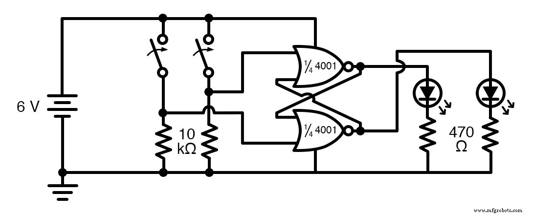
SCHEMATIC DIAGRAM
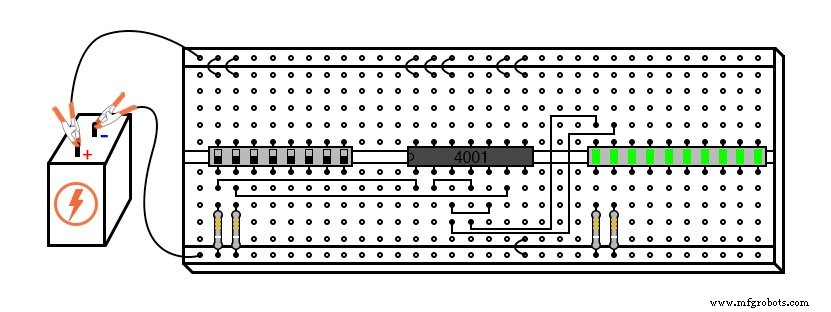
ILLUSTRATION
INSTRUCTIONS
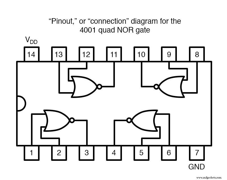
The 4001 is a CMOS quad NOR gate with pin assignments identical to the 4011 quad NAND gate. Its pinout is shown below:
When two NOR gates are cross‑connected as illustrated, the output feeds back to the input, creating positive feedback and hysteresis. This feedback endows the circuit with a simple form of memory: once set, it will retain its state until a new input forces a change.
Label the left switch as Set and the right switch as Reset. The left LED represents the Q output; the right LED represents Q‑not. A high Set and low Reset forces Q high and Q‑not low (the set state). Conversely, a high Reset and low Set forces Q low and Q‑not high (the reset state). When both inputs are low, the latch retains its previous state – the latched state. If both inputs are high, the outputs are forced to the same logic level, which violates the complementary requirement and is termed the invalid state.
To observe the latch’s behavior at power‑up, set both switches to the off position (low inputs), disconnect one battery lead, then re‑connect it rapidly while watching the LEDs. The circuit will race: each gate attempts to drive the other high; the faster gate wins, and its state is latched. Because of inherent asymmetries, the power‑up state is often consistent, but repeated cycling may reveal occasional opposite states, illustrating the unpredictability of race conditions.
Race conditions can be problematic in real systems, especially when a defective or slower gate consistently wins the race, causing a stable yet incorrect state. Changing components can alter the race outcome, leading to subtle bugs that are hard to trace.
To eliminate reliance on an unpredictable power‑up state, designers typically use an external reset or set mechanism to force the latch into a known state during startup.
An instructive modification is to replace one 470 Ω LED drop resistor with a lower value, such as 100 Ω. This increases LED brightness and introduces a load asymmetry that affects the latch’s ability to maintain its state. When operating the switches through all four input combinations, you’ll notice that the latch fails to hold in one of the states when both inputs are low. Measuring the output voltage of the high gate with a voltmeter shows that the gate with the 100 Ω load produces a weaker high level that falls below the threshold required to drive the other NOR gate’s input. In contrast, the 470 Ω gate maintains a stronger high level that successfully latches the circuit.
These observations underscore why it’s preferable to use a voltmeter as a logic probe: a voltmeter gives a quantitative voltage reading, revealing weak signals that a simple logic probe might miss. This is especially important when mixing different logic families (e.g., TTL vs. CMOS), where voltage thresholds can differ significantly.
Industrial Technology
- NOR Gate SR Latch: Building and Understanding Digital Memory
- Building an Enabled NAND‑Gate SR Latch: Parts, Design, and Operation
- Building a NAND‑Based Set‑Reset Flip‑Flop Circuit
- Understanding TTL NOR and OR Gates: Circuit Analysis and Conversion
- Gate Universality: Replicating Any Logic Function with NAND or NOR Gates
- The S‑R Latch: Fundamentals, Race Conditions, and Practical Applications
- Gated SR Latch: Enhancing Logic Control with an Enable Input
- Automated Railway Gate Controller: Arduino Circuit & Source Code
- Solid State Relays (SSRs): A Professional Guide for Electronics Engineers
- Transistor Latch Explained: A Complete Guide to Building and Using Latch Circuits