


Simple Analog Averaging Circuit: A Practical Voltage Averager
Simple Analog Averaging Circuit
Components & Materials
- Three batteries of differing voltages
- Three identical resistors (10 kΩ–47 kΩ)
When selecting resistors, use an ohmmeter to pick three that are as close in value as possible. Precision is critical for this experiment.
Cross‑References
“Lessons In Electric Circuits,” Volume 1, Chapter 10: “DC Network Analysis.”
Learning Objectives
- Demonstrate how a resistor network can average three voltage signals
- Apply Millman’s Theorem to a practical circuit
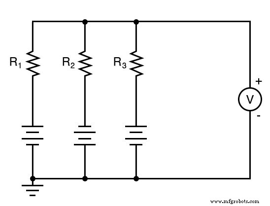
Schematic Diagram
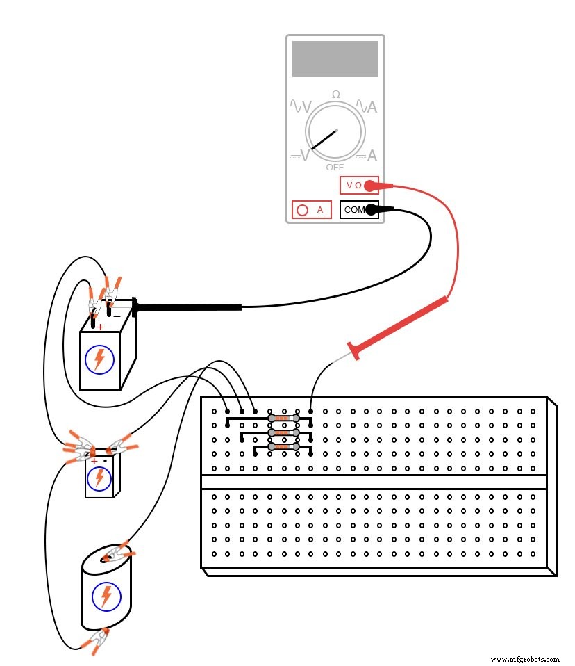
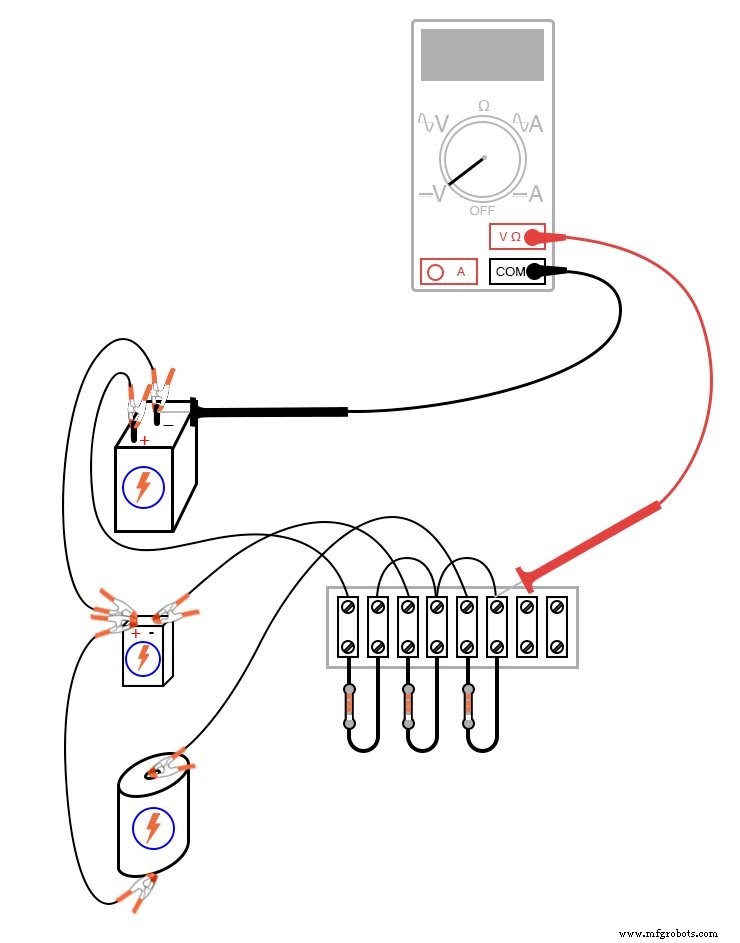
Illustration
Instructions
This deceptively simple circuit performs a single mathematical operation—averaging three voltage signals. Build the circuit exactly as shown and measure each battery’s voltage with a voltmeter. Write down the readings (E1, E2, E3), then calculate the algebraic average: (E1 + E2 + E3)/3.
When measuring, keep the black probe on the circuit’s common ground (the battery side connected by jumper wires) and the red probe on the opposite terminal. Note the polarity: one battery is wired “backward” relative to the other two; its voltage will appear negative on a correctly connected meter.
Connecting the voltmeter to the node indicated in the schematic should display the algebraic average of the three battery voltages. With closely matched resistors, the output voltage will match the calculated average with high precision.
Removing a battery changes the output: the circuit will average the remaining voltages, or if the disconnected battery’s wires are bridged, it will average the two remaining voltages plus 0 V, producing a smaller output.
The circuit’s speed is limited only by the propagation of voltage through the resistive network—effectively the speed of light. While analog computers like this one are not as precise as digital systems, they excel at continuous‑time calculations such as differentiation and integration, once amplified and combined with additional circuitry.
Computer Simulation
Schematic with SPICE node numbers:

Netlist (create a text file containing the following exactly):
Voltage averager v1 1 0 v2 0 2 dc 9 v3 3 0 dc 1.5 r1 1 4 10k r2 2 4 10k r3 3 4 10k .dc v1 6 6 1 .print dc v(4,0) .end
This SPICE model lets you simulate the analog averaging operation on a digital computer—useful for learning about circuit simulation rather than for practical number crunching.
Related Worksheets
- Millman’s Theorem Worksheet
Industrial Technology
- Building and Troubleshooting a Basic 6‑V Battery‑Lamp Circuit
- PC Oscilloscope: Build a Low‑Cost Waveform Analyzer Using Your Computer
- Build a High‑Gain Differential Amplifier That Works as an Op‑Amp
- Tachogenerators: Precision Speed Measurement for Industrial Motors and Equipment
- Understanding AC Waveforms: Sine Waves, Frequency, and Oscilloscope Basics
- Vector Addition and AC Voltage Superposition: A Practical Guide
- Beyond Sine Waves: How Power Electronics Shape Harmonics
- Simple Motor‑to‑Generator Conversion: Turning a Toy Motor into a LED Power Source
- DIY Generator: Build a Simple Alternator from Recycled Materials
- Laser Cutting vs. Conventional Methods: Choosing the Best Sheet Metal Cutting Technique