


Beyond Sine Waves: How Power Electronics Shape Harmonics
Every periodic, non‑sinusoidal waveform can be expressed as a sum of sinusoidal components—a principle known as Fourier series. While the square wave is the textbook example, real‑world power electronics routinely generate a wide array of complex shapes.
Devices such as transistors and silicon‑controlled rectifiers (SCRs) modulate their resistance almost instantaneously in response to a control signal. The resulting voltage and current waveforms are sharply “chopped” versions of the clean, pure sine‑wave AC supplied by the grid, producing waveforms that bear little resemblance to the original source.
These distorted waveforms alter the voltage across downstream components through the voltage drops that arise when non‑sinusoidal currents flow through circuit impedances.
Nonlinear Components and Harmonic Generation
In power electronics, components that distort the AC sine shape are referred to as nonlinear. SCRs and other switching devices are favored for their high‑power handling and low heat dissipation, but their rapid on/off action introduces significant harmonic content.
Although energy‑efficient, these harmonics can lead to erratic circuit behavior. A distorted AC waveform is mathematically equivalent to a series of higher‑frequency sinusoids (harmonics). If the designer neglects these, transformers and motors may overheat—a phenomenon increasingly reported in industries with heavy “switching” loads such as data centers and LED lighting.
Below we examine common waveforms, their harmonic spectra, and the practical implications of these distortions. Fourier analysis in SPICE provides a clear, visual representation of how each rectification method shapes the frequency content.
Half‑Wave Rectification
The simplest AC‑to‑DC conversion uses a single diode to block half of the AC cycle. The result is a waveform that carries the same positive half‑cycles but zeros out the negative portions, as shown in the schematic below.
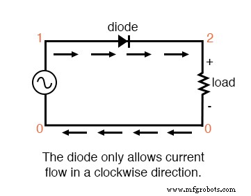
Half‑wave rectifier
halfwave rectifier
v1 1 0 sin(0 15 60 0 0)
rload 2 0 10k
d1 1 2 mod1
.model mod1 d
.tran .5m 17m
.plot tran v(1,0) v(2,0)
.four 60 v(1,0) v(2,0)
.end
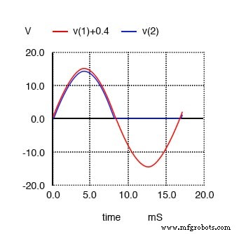
Half‑wave rectifier waveforms. V(1)+0.4 shifts the sine wave input V(1) up for clarity.
First, we analyze the source sine wave in SPICE:
fourier components of transient response v(1)

DC component = 8.016E-04
harmonic   frequency  fourier    normalized   phase   normalized
no         (hz)      component   component    (deg)   phase (deg)
1          6.000E+01   1.482E+01   1.000000    -0.005  0.000
2          1.200E+02   2.492E-03   0.000168  -104.347 -104.342
3          1.800E+02   6.465E-04   0.000044   -86.663  -86.658
4          2.400E+02   1.132E-03   0.000076   -61.324  -61.319
5          3.000E+02   1.185E-03   0.000080   -70.091  -70.086
6          3.600E+02   1.092E-03   0.000074   -63.607  -63.602
7          4.200E+02   1.220E-03   0.000082   -56.288  -56.283
8          4.800E+02   1.354E-03   0.000091   -54.669  -54.664
9          5.400E+02   1.467E-03   0.000099   -52.660  -52.655
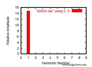
Fourier analysis of the sine wave input
As expected, the sine wave contains a dominant fundamental component with negligible harmonics and DC offset. SPICE’s finite simulation window introduces a tiny error, but the result is practically a pure tone.
Now, consider the voltage across the load resistor after half‑wave rectification:
fourier components of transient response v(2)

DC component = 4.456E+00
harmonic  frequency   fourier    normalized   phase    normalized
no         (hz)      component   component    (deg)    phase (deg)
1          6.000E+01   7.000E+00   1.000000    -0.195    0.000
2          1.200E+02   3.016E+00   0.430849   -89.765   -89.570
3          1.800E+02   1.206E-01   0.017223  -168.005  -167.810
4          2.400E+02   5.149E-01   0.073556  -87.295   -87.100
5          3.000E+02   6.382E-02   0.009117  -152.790  -152.595
6          3.600E+02   1.727E-01   0.024676  -79.362   -79.167
7          4.200E+02   4.492E-02   0.006417  -132.420  -132.224
8          4.800E+02   7.493E-02   0.010703  -61.479   -61.284
9          5.400E+02   4.051E-02   0.005787  -115.085  -114.889
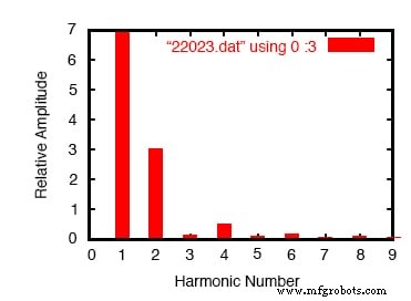
Fourier analysis of half‑wave output
Here, the rectification introduces significant even‑harmonics and a DC offset of 4.456 V. The presence of higher‑frequency sinusoids can increase losses in downstream components and potentially excite resonances.
Full‑Wave Rectification
Full‑wave conversion, often implemented with a bridge of four diodes, utilizes the entire AC cycle, flipping the negative half so that current always flows in the same direction. The schematic is shown below.
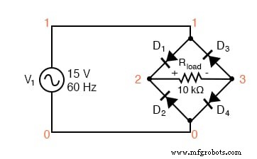
Full‑wave bridge rectifier
fullwave bridge rectifier
v1 1 0 sin(0 15 60 0 0)
rload 2 3 10k
d1 1 2 mod1
d2 0 2 mod1
d3 3 1 mod1
d4 3 0 mod1
.model mod1 d
.tran .5m 17m
.plot tran v(1,0) v(2,3)
.four 60 v(2,3)
.end
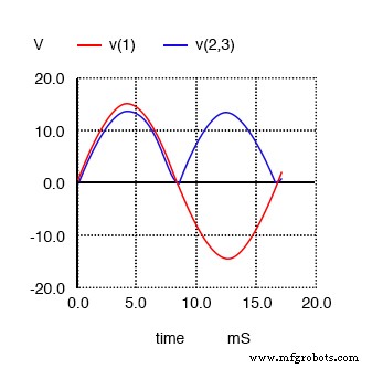
Waveforms for full‑wave rectifier
fourier components of transient response v(2,3)

DC component = 8.273E+00
harmonic   frequency  fourier    normalized   phase   normalized
no         (hz)      component   component    (deg)   phase (deg)
1          6.000E+01   7.000E-02   1.000000   -93.519   0.000
2          1.200E+02   5.997E+00   85.669415  -90.230   3.289
3          1.800E+02   7.241E-02   1.034465  -93.787  -0.267
4          2.400E+02   1.013E+00   14.465161  -92.492   1.027
5          3.000E+02   7.364E-02   1.052023  -95.026  -1.507
6          3.600E+02   3.337E-01   4.767350  -100.271 -6.752
7          4.200E+02   7.496E-02   1.070827  -94.023  -0.504
8          4.800E+02   1.404E-01   2.006043  -118.839 -25.319
9          5.400E+02   7.457E-02   1.065240  -90.907   2.612
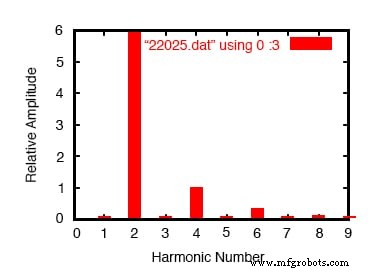
Fourier analysis of full‑wave rectifier output
The full‑wave bridge introduces a pronounced second harmonic—over 85 times larger than the fundamental—alongside a DC component of 8.273 V. The resulting spectrum is far richer than the half‑wave case, demonstrating how even a simple change in topology can dramatically alter harmonic content.
Understanding these spectral characteristics is essential for designing robust power supplies, ensuring compliance with standards such as IEC 61000‑4‑7, and preventing unwanted electromagnetic interference (EMI).
While the mathematics of Fourier transforms may be advanced, the practical takeaway is clear: every switching action creates harmonics that can ripple through a system, affecting efficiency, reliability, and compliance.
In the next section, we will discuss the real‑world consequences of these harmonics on motors, transformers, and overall system performance.
REVIEW:
- Any repetitive waveform can be expressed as a sum of sinusoids; the particular mix defines its shape.
- Rectification—both half‑wave and full‑wave—is a primary source of harmonics in industrial power systems.
Industrial Technology
- Simple Analog Averaging Circuit: A Practical Voltage Averager
- Exploring Advanced Diode Technologies: Varicaps, PINs, IMPATT, Gunn, and More
- Specialized Motors: Shaded‑Pole, Servo, Hysteresis, and Eddy‑Current Clutch Applications
- Ensuring Your Training Truly Delivers: A Reliability Engineer’s Guide
- Transparent Wood & Carbon-Neutral Innovations: The Future of Sustainable Materials
- Advanced Tooling Solutions for Swiss-Type Machines & Small Parts Manufacturing
- Manual vs. Automatic Part Cost Calculations: Which Approach Saves You Money?
- Arduino Alternatives: Top Microcontroller Boards to Try
- Anodizing Metals: A Professional Guide for Manufacturers
- Telescoping Stackers & Radial Conveyors: Durable Solutions for Heavy Material Handling