


Serial‑In, Parallel‑Out Shift Registers: Converting Serial Data to Parallel for Efficient I/O Expansion
A serial‑in, parallel‑out (SIPO) shift register shares the data‑shifting core of its serial‑in, serial‑out counterpart, but it exposes every internal stage as a separate output pin. This makes it an ideal solution for converting a single serial data line into multiple parallel outputs.
How It Works
When four bits are fed serially into the device, one clock pulse per bit shifts the data through successive stages. After the fourth pulse, the four bits appear simultaneously on the outputs Q_A to Q_D:
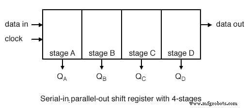
This simple mechanism is often visualised as a serial‑in, serial‑out register with tap points on each stage.
Serial‑In, Parallel‑Out vs. Serial‑In, Serial‑Out
Manufacturers typically offer SIPO devices up to 8‑bit width because a wider parallel output would require an impractical number of pins. In contrast, serial‑in, serial‑out shift registers can exceed 8 bits, up to 64, and are used when only a single serial line is needed.
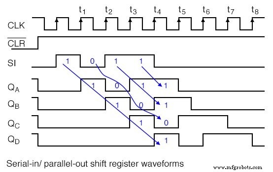
The device is cleared by the active‑low CLR input, which resets all internal flip‑flops before new data is loaded.
Common SIPO ICs from Texas Instruments
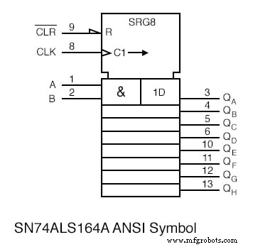
- SN74ALS164A – 8‑bit SIPO shift register
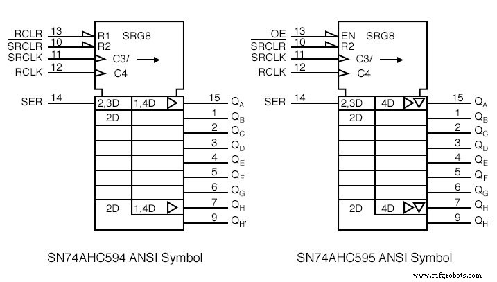
- SN74AHC594 – 8‑bit SIPO with output register
- SN74AHC595 – 8‑bit SIPO with output register and tri‑state outputs
- CD4094B – 8‑bit latching shift register (3‑15 VDC)
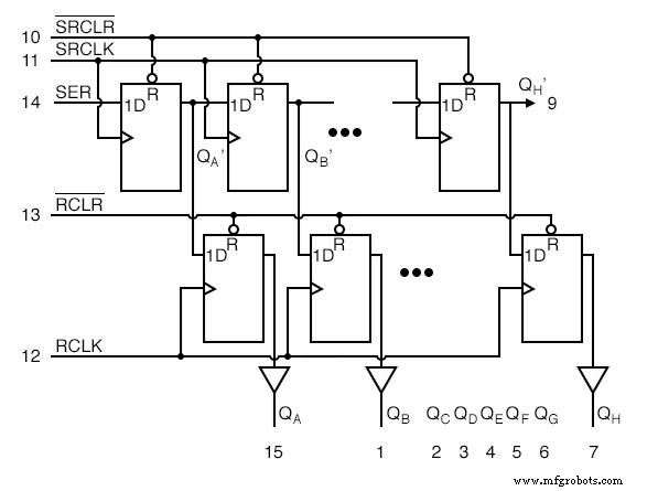
The 74AHC594’s internal architecture features two separate clocks: SRCLK for the shift register and RCLK for the output register. This separation allows the output to remain stable while new data is shifting in, which is critical when driving relays, motors, or other actuators.
After data has been shifted into the upper 8‑bit register, a rising edge on RCLK latches the data into the output register, keeping the outputs unchanged during subsequent shifts.
Similarly, the 74AHC595 replaces the output register clear with an output enable OE, providing a tri‑state buffer that can be disconnected during system power‑up.
Practical Applications
In real‑world systems, SIPO shift registers are used to drive remote displays, LED indicators, or other parallel‑input devices from a microcontroller that has limited I/O pins. For example, an alarm system can send serial data to a remote panel, where the SIPO expands the data into eight LED outputs.
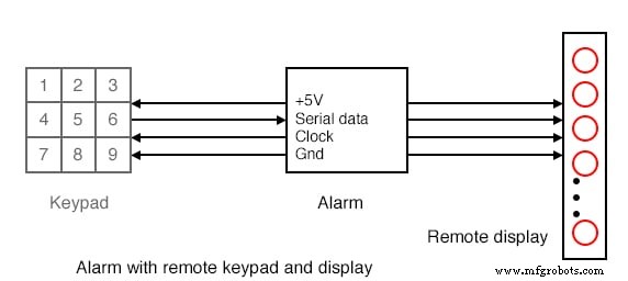
By using only five wires—clock, serial data, strobe (or RCLK), power, and ground—the number of physical connections between the main board and the remote panel is drastically reduced, improving reliability and simplifying cable management.
For larger displays or actuator arrays, multiple SIPO devices can be cascaded. The Q_H output of the first register feeds the SER input of the next, while the SRCLK and RCLK pins are tied together.
LED indicators are often multiplexed using SIPO registers, allowing a single serial input to control many segments or digits without needing a dedicated pin per LED.
In summary, serial‑in, parallel‑out shift registers provide a cost‑effective, scalable way to expand parallel outputs from a serial data stream, making them indispensable in embedded system design.
Related Worksheets
- Shift Registers Worksheet
Industrial Technology
- Low‑Voltage AC Power Supply: Phase‑Shift Circuit Components & Best Practices
- Converting Decimal Numbers to Binary, Octal, and Hexadecimal: A Practical Guide
- Shift Registers: Fundamentals, Applications, and Design Variants
- Serial‑In, Serial‑Out Shift Registers: Fundamentals and Practical Applications
- Parallel‑to‑Serial Shift Registers (PISO): Design, Operation, and Applications
- Universal Shift Registers: Parallel‑In/Parallel‑Out with Bidirectional Shift Control
- Successive Approximation ADC – A Faster, Accurate Digital-to-Analog Conversion Method
- Understanding AC Phase Shift: How Waveforms Lead and Lag
- Verilog N‑bit Bidirectional Shift Register – Design and Implementation
- Controlling 32 LEDs with Arduino Nano and 4x 74HC595 Shift Registers – A Beginner’s Guide