


Verilog Basics: Designing Your First AND Gate
Verilog is a hardware description language (HDL) that empowers engineers to model, simulate, and synthesize digital logic for FPGAs and ASICs. Alongside its close cousin VHDL, Verilog is the industry‑standard language for both academic curricula and commercial product development.
If you’re new to the world of programmable logic or silicon design, this guide walks you through the basics of Verilog and shows you how to build a simple AND gate—a foundational element of every digital system.
Unlike high‑level software languages such as Java or C, Verilog describes hardware at the gate level. The result is code that can be mapped directly to silicon, giving designers fine‑grained control over timing, power, and area.
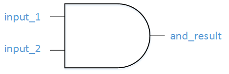
Below is a diagram of a classic two‑input AND gate that we’ll model in Verilog.
Let’s dive into the Verilog implementation.
In Verilog, the building block is the wire. For this example, we’ll treat a wire as a binary signal that can only be 0 or 1.
  wire and_temp;
  assign and_temp = input_1 & input_2;
The first line declares a wire named and_temp. The second line assigns it the result of a logical AND between input_1 and input_2. In Verilog, the ampersand (&) is the Boolean AND operator.
All signals that a module exposes are listed in its module header. The module keyword introduces a self‑contained block of code with defined inputs and outputs.
module example_and_gate
(
    input_1,
    input_2,
    and_result
);

    input  input_1;
    input  input_2;
    output and_result;
Finally, we wire the internal and_temp signal to the external and_result output and close the module.
///////////////////////////////////////////////////////////////////////////////
// File Downloaded from https://www.nandland.com
///////////////////////////////////////////////////////////////////////////////
module example_and_gate
(
    input_1,
    input_2,
    and_result
);

    input  input_1;
    input  input_2;
    output and_result;

    wire and_temp;

    assign and_temp = input_1 & input_2;

    assign and_result = and_temp;

endmodule // example_and_gate
Congratulations—you’ve written your very first Verilog module! While HDL syntax can feel verbose compared to conventional software, it offers unparalleled precision for hardware design. With practice, you’ll be able to implement everything from simple logic gates to full‑blown graphics pipelines.
Verilog
- Foundations and Advancements of AC Motor Technology
- Master Verilog: Complete Tutorial for Digital Circuit Design
- Mastering Verilog Syntax: Key Rules & Best Practices
- Verilog Module Basics: Structure & Syntax
- Understanding Verilog Assign Statements: Continuous Signal Assignment Explained
- Mastering Verilog Concatenation: A Practical Guide
- Understanding Verilog Always Blocks: Syntax & Sensitivity Lists
- Verilog Initial Blocks: Purpose, Syntax, and Non‑Synthesizable Use
- Mastering Verilog Generate Blocks: Dynamic Module Instantiation & Conditional Design
- Understanding Verilog Assignments: Types, Syntax, and Best Practices