


Build Your Own ESR Meter: A Complete Guide for Electronics Enthusiasts
About DIY ESR Meter, Every trade has its unique set of tools. In the case of electronics, you should at least have a multimeter, screwdriver, cutter, and soldering iron and wires.
The best part is you can find these tools in any electronics shop and for an affordable price. However, there are other important but expensive tools you’ll need as you walk down the path of elections.
And among these tools is the ESR meter.
So, in this article, we will show you how to build your ESR meter with a ready-made strip/ Vero board with the same result as the ESR meters on the market.
Ready? Let’s learn!
Stripboard
What is ESR?
Capacitors are not immune to degradation. When you see some undesirable effects, it’s because of Equivalent Series Resistance (ESR). Why? Capacitors have limited internal resistance because of the materials manufacturers use to build them.
Also, various types of capacitors come with different ESR ranges. So, it’s critical to measure the equivalent series resistance of your capacitors.
What is An ESR Meter?
When it comes to measuring capacitors, capacitance meters (digital or analog) can mislead you. With this tool, you might think a faulty capacitor is good. Plus, if you don’t test for ESR on a capacitor, you’ll miss a bad capacitor and fail to make any repairs. So, what you’ll need is an ESR meter.
An ESR meter is a two-terminal measuring tool with the primary purpose of measuring the ESR of capacitors. Usually, bad capacitors have high ESR readings that you can’t measure with a regular digital capacitance meter or multimeter.
That’s not all.
You can use an ESR meter without removing the capacitors from your circuit.
Here’s the best part.
You can use an ESR for other experiments like checking low ohms resistors such as 0.33 ohm and 0.22 ohm, locate short circuits on printed circuit boards, speaker amplifiers, and check the condition of both normal and rechargeable batteries.
How Does the ESR Meter Work?
Various factors contribute to power loss in capacitors. You can sum these factors up as ESR. To fully understand how an ESR meter works, let’s take a look at the components:
Oscillator
The oscillator is responsible for supplying the AC signal required for driving current through the capacitor you’re testing. A good example of an oscillator circuit runs at approximately 100 kHz.
Also, 100 kHz is the industry standard for making ESR measurements. One section of this circuit acts as a phase-shift oscillator. It’s easy to implement, and it shows you an excellent approximation of a sine wave.
The other section works as an amplifier and a buffer. Due to the phase-shift oscillator having a high output impedance, this section prevents the oscillator circuit from overloading. Also, you can adjust the level of the 100 kHz signal with the gain-control potentiometer.
The ESR Detector
The ESR detector is where most of the action happens. The first section is a voltage-to-current converter that converts the 100 kHz signal from the oscillator to a peak-to-peak current of about 7Ma.
So, you can connect the CUT (capacitor under test) inside the feedback loop of this stage. Also, you can do this with two front panel binding posts so the CUT receives the same current.
The Power Conversion Section
In this section, a single-supply approach requires you to provide a virtual ground reference throughout the ESR meter. So, in this stage, a conventional three-terminal voltage regulator (at the input) supplies a +5v bus.
On the other hand, the -5v bus gets its supply from a dandy component that dishes out a DC voltage equal to the magnitude (but with a reversed polarity) to the input.
How it Works
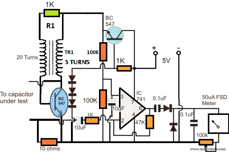
ESR Circuit Diagram
First, the TR1 on the above diagram and the fastened NPN transistor create simple feedback that triggers a blocking oscillator. The blocking oscillator starts oscillating at a high frequency.
Additionally, the oscillations create a consistent magnitude of the voltage over the 5 turns of the secondary transformer. Also, the oscillator applies the induced high frequency across the CTU.
Also, you can see an op-amp joined with the low voltage high-frequency feed. Plus, it works there as a voltage amplifier.
If the ESR is absent or you have a working capacitor, then the meter will suggest a complete deflection. Thus, it shows a tiny ESR over the capacitor, which in turn goes down to zero for various capacitors—with different levels of ESR.
Now, a lower ESR might cause a moderately higher current to build up over the op-amp inverting sensing input. Also, it correspondingly displays on the meter along with a lofty degree of deflection and vice versa.
Additionally, the higher BC547 transistor works as a usual voltage collector and regulator stage. For this reason, the transistor can handle the oscillator stage with a minimal 1.5 volts. Also, other electronic devices around the CUT will stay under no stress from the test frequency of the ESR meter.
Also, it’s easy to calibrate the meter. Plus, if you keep the test leads low, the 100k pre-set close to the uA meter adjusts until it achieves a wholesome deflection on the meter dial.
Afterward, you can verify various capacitors with lofty ESR values on the meter and approximately smaller degrees of deflection.
Finally, the transformer stands on top of a ferrite ring. Also, it uses a thin magnet with various turns on the diagram.
How to Build Your ESR Meter
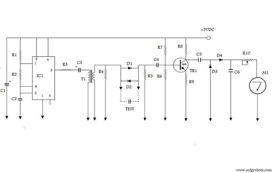
ESR Circuit diagram
In this section, the above circuit is what we will learn how to make. The circuit gets its power from a single 9V battery. You can use a low-cost LDO as a replacement so you can get the maximum battery life as the voltage drops over time.
Plus, the LM2936 is not so expensive and will carry out operations even when it drops to 5.5V. Also, we added an LED on/off indicator after the switch—though we didn’t show it in the above diagram.
Circuit Components
- C1- 100uf
- C2 – 470PF
- C3 – 10uf
- C4 – 0.1uf
- C5 – 100nf
- C8 – 100nf
- R1 – 1K
- R2 – 10K
- R3 – 150
- R4 – 12
- R5 – 12
- R6 – 27K
- R7 – 100K
- R8 – 2.2K
- R9 – 100
- R10 – 10K pot
- ICI – 555
- TR1 – 3904
- T1 – 2.1 transformer
- D1 – IN4007
- D2- IN4007
- D3 – IN4148
- D4 – IN4148
Circuit Operation
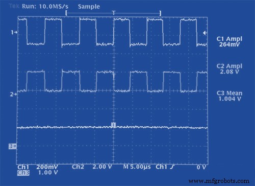
Let’s look at some illustrations to better understand how this circuit works. So, we will illustrate with the waveforms at points 1, 2, and 3 with a shortened lead of ESR (0) and with a high ESR (5.6) Ohm. Here, the waveforms correspond to related channels and the oscilloscope shot.
Also, the signal at the capacitor/resistor divider’s output is about 232 mV peak-to-peak. Plus, the transistor multiplies the output value by a factor of over 10. Additionally, channel 3 holds the filtered and rectified signal (about 1.35 V).
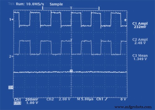
Waveforms with ESR (0)
So, here’s what the meter looks like in full depletion after adjusting the 10k potentiometer.
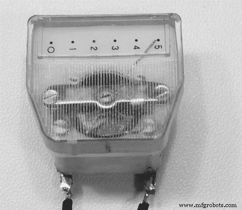
Full depletion of ESR (0)
On the other hand, when a capacitor has a high ESR (5.6 Ohm), you can insert it across the test leads. So, the output voltage of point 2 reduces, and also the resulting DC level at point 3.
Waveforms with ESR (5.6 Ohm)
Here’s what the meter looks like with depletion of ESR = 5.6 Ohm.
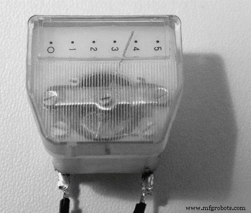
Meter for the depletion of ESR (5.6 Ohm)
Building the Circuit
This circuit is so easy you can use a perf board for assembly. Though it won’t be easy finding an adequate signal transformer for T1/E1 transmission links, you might have one in your parts bin.
A great alternative and solution to this problem are transformers from switching power supplies (PC ATX supplies). Another alternative is a larger turn ratio. But, there’s a catch. You would have to adjust the 150 Ohm series resistor to a higher value.
Here’s what the fully assembled circuit looks like:
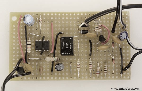
Circuit Assembly
Once you’ve assembled the circuit, you can do the final assembly inside a metallic box. Also, you can use an audio jack and shielded audio cable to connect your test probes. Plus, you should connect the ground (shield) to the metallic case.
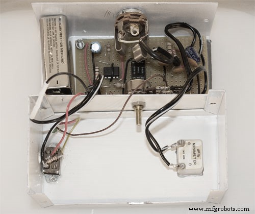
Final Circuit Assembly
Limitations of Almost Any ESR Meter
Here are some limitations of any ESR meter:
1. If you have any capacitor with an internal short circuit, the readings of the ESR meter will mislead you into thinking it has a low-value ESR.
2. The meter is not the best option for testing capacitors with less than 30 microfarads. If the capacitor under test is too low, the measuring reactance frequency becomes highly significant. So, this results in an excessive ESR.
3. There can be errors from long test leads of the CUT. How? Because the ESR is a low range ohmmeter.
Rounding Up
Building an ESR is an easy and fun project. The best part is, you can achieve this with commonly found parts in an electronic lab. The ESR meter is the go-to for any electronics repair technicians, hobbyists, designers, and engineers.
ESR is an important attribute of capacitors bigger than 1 microfarad. Plus, you’ll need the ESR tester if you want to make measurements that are impossible with the standard digital capacitance meter.
Well, that rounds up everything you need to know about ESR meters and how to build them. If you have questions or suggestions, feel free to reach us. We’ll be happy to help.
Industrial Technology
- Mastering Laser Cutting: Precision, Power, and Practical Guidance
- Process Cooling Explained: Benefits, Methods, and Industrial Applications
- DIY Float Switch: A Complete Guide to Building and Installing Your Own Water Level Sensor
- The Ultimate Guide to Remote Control Car Circuits: Build, Troubleshoot, and Master Your RC Vehicle
- AM Loop Antenna Guide: Boost Signal Quality and Reduce Noise
- Understanding Transformers: Key Principles & Practical Applications
- RK3399 Review: Key Features, Performance, and Why It Beats Raspberry Pi
- Mastering MFD Capacitors: Key Insights & Applications
- Mastering STL Files: A Complete Guide for 3D Printing
- Hot Stamping 101: The Complete Guide to Elegant Metal Foil Design