


Mastering Notch Filter Design: Precision Noise Suppression for Reliable Electronics
Noise and interference are common when dealing with electrical devices because different circuits produce varying signal frequencies that clash. Such issues are prevalent in communication devices, which get easily affected by power lines. If you are experiencing such issues, there is a way to filter out the unwanted frequencies using a notch filter design. There are different types of notch filters, and each has a unique circuit design that requires specific components to build.
In this article, we will look at them in detail to enable you to build the correct circuit.
What Is A Notch Filter?
Also known as a band rejection filter or band-stop filter, a notch filter is a device that creates a high level of attenuation on a narrow notch. It rejects this band of frequencies but allows all others below or above the blocked range to transmit.
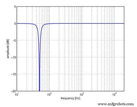
Graph showing the frequency response of a 50Hz audio filter. Note the narrow V-shape of the blocked frequencies.
Source: Wikimedia Commons.
The device comes in handy to filter out particular noise, such as the 60Hz hum coming from an AC power source.
Notch Filter Characteristics
Notch filters have three attributes:
- Narrow bandwidth (stopband)
- Great attenuation depth
- High Q
To achieve high Q, you need an almost infinite attenuation depth and a high gain operational amplifier in the circuit.
Notch Filter Types
Notch filter designs have three components. A low-pass filter attenuates the high frequencies, a high-pass filter blocks the low frequencies, and a summing amplifier combines the results.
However, there are different notch filter types, and each has a unique circuit design. They include:
Active Notch Filter
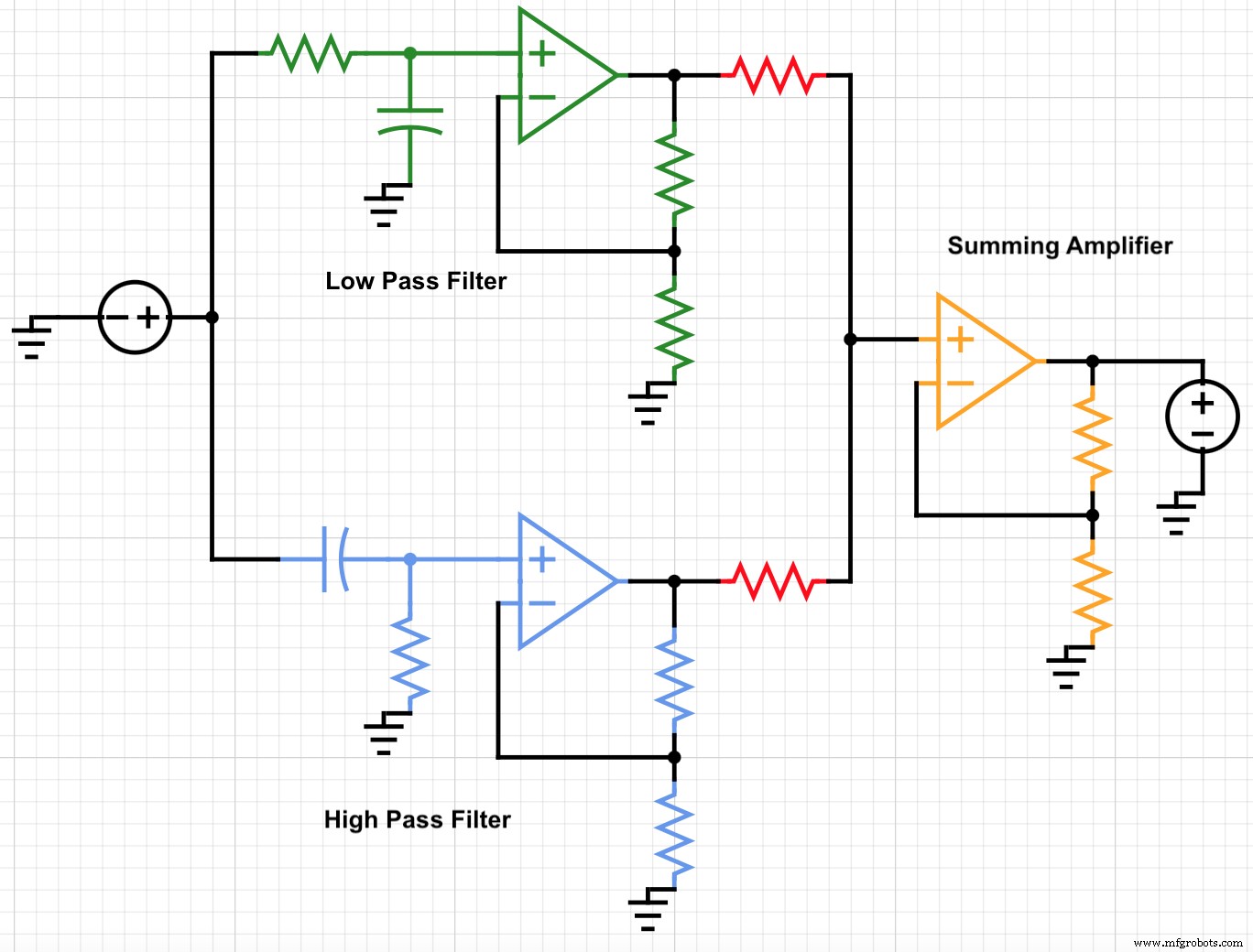
An active notch filter circuit diagram
The green part forms the low pass filter in this active filter, while the blue part forms the high pass filter. These get summed up by the op-amp (orange components).
Passive Notch Filter
Unlike an active notch filter, this type only has passive components. It lacks amplifiers, which form the active part of the circuit.
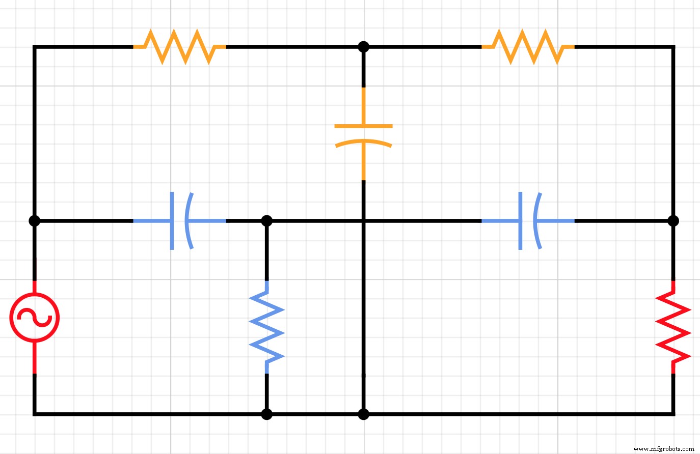
Passive notch filter circuit diagram showing the low and high pass filters in T configurations
The orange parts form the low pass filter section in the diagram, while the blue components form the high pass filter.
RLC Notch Filter
As the name suggests, an RLC notch filter is a passive type because the circuit only has a resistor (R), inductor (L), and capacitor (C).
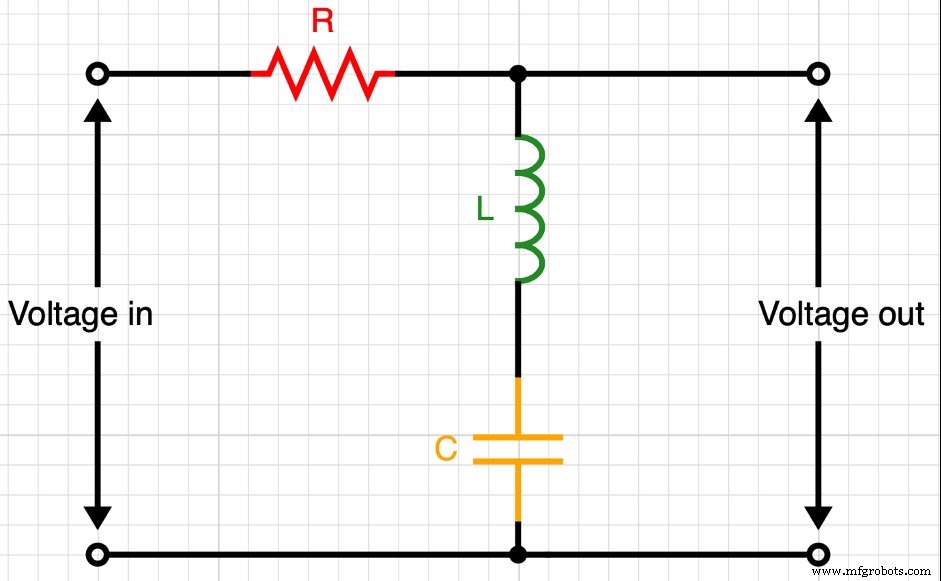
An RLC notch filter
Butterworth Notch Filter
A Butterworth notch filter produces a response that is as flat as possible, making it reliable and highly accurate. Most medical equipment, such as ECGs, have the device.
4th order Butterworth low-pass filter
FM Notch Filter
FM notch filters help to reject strong FM signals that cause receiver saturation. Frequency modulation in the same band has increased, mainly due to localized audio broadcasts, so this device is crucial for reducing noise.
A VHF FM notch filter
The other types include optical, RF, and inverse notch filters. There may be more, but all have an active or passive notch filter as the underlying circuit. The only way to differentiate between the two is if the circuit design has an active component (amplifier circuit) or not.
Notch Filter Design Example
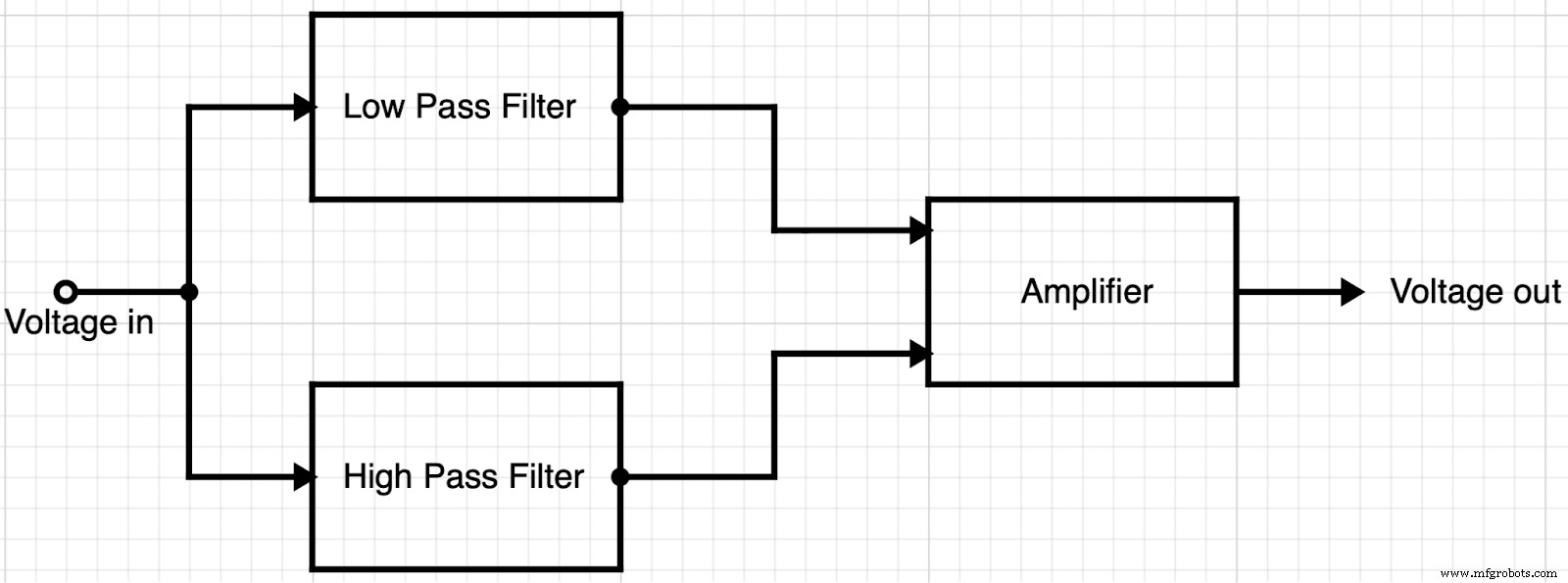
The basic design of a notch filter
As stated earlier, a notch filter has three main components: a low pass filter, a high pass filter, and an amplifier. Combined, the three attenuate a narrow and specific frequency range.
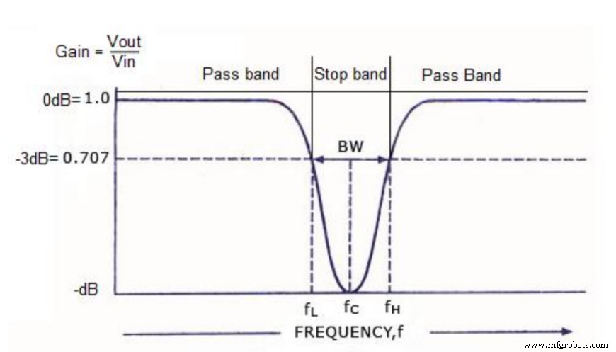
Graph response showing the narrow V stopband of a notch filter
Source: Wikimedia Commons.
The most common notch filter topology is the basic twin-T notch filter design. It is a combination of two RC branches.
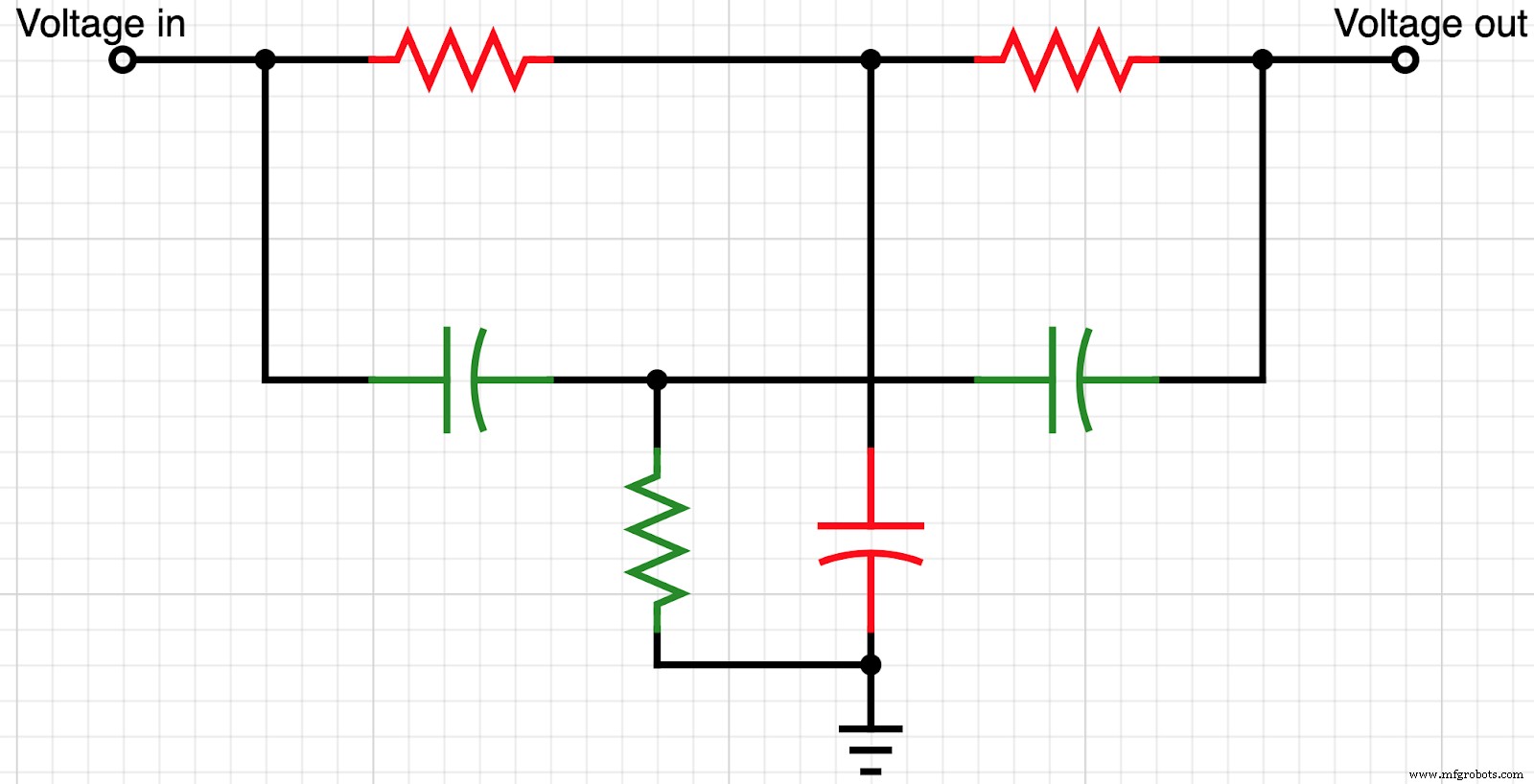
A basic twin-T notch filter circuit
The upper T configuration (in red) is the low pass filter, while the lower T (in green) is the high pass filter.
However, if you want to attain a narrower level of rejection with a high attenuation level, you need to introduce an operational amplifier.
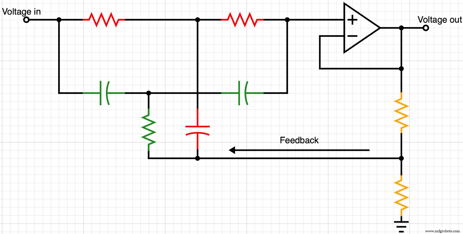
A twin-T notch filter with an operational amplifier. The two resistors in orange form the voltage divider
The circuit still has one major problem. It increases the gain after the V attenuation in the response curve. Therefore, you need to introduce another operational amplifier to keep the circuit from altering the passband.
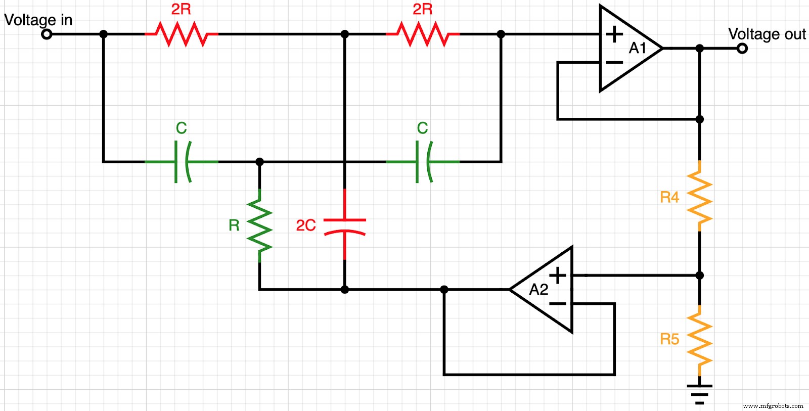
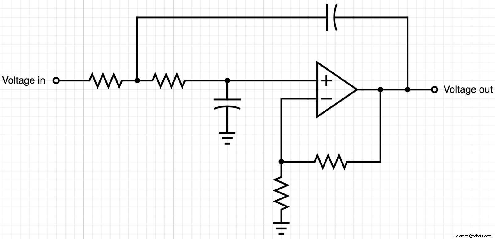
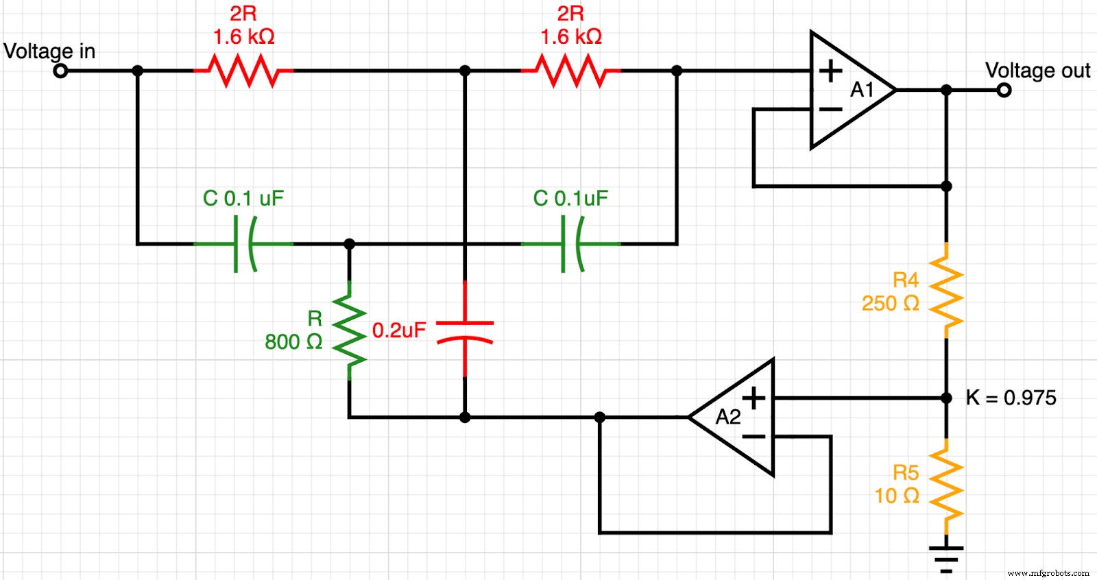
Two op-amp notch filter design
Design Example
Say we want to design two operational amplifiers with a 1kHz notch frequency and a 3dB bandwidth of 100Hz. Consider the value of the high-pass filter capacitors to be 0.1uF.
We can use the formula for getting the notch filter frequency, which is:
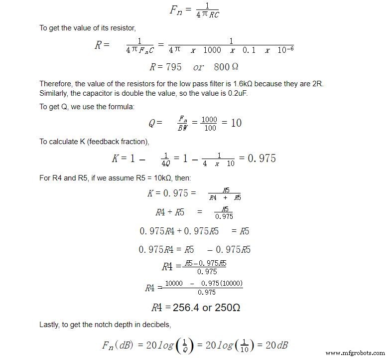
Therefore, we can design the active notch filter for a 20dB notch depth as follows:
A two op-amp notch filter for a 20dB notch depth
Design An RLC Type Notch Filter
Another example worth looking at is the RLC notch filter. Instead of having a twin-T design with six components, this one only has three: a resistor, inductor, and capacitor.
If the task is to design a circuit with 23 kHz and 25 kHz as the cut-off frequencies, here’s how to go about it.
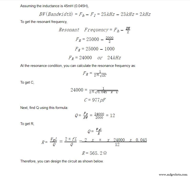
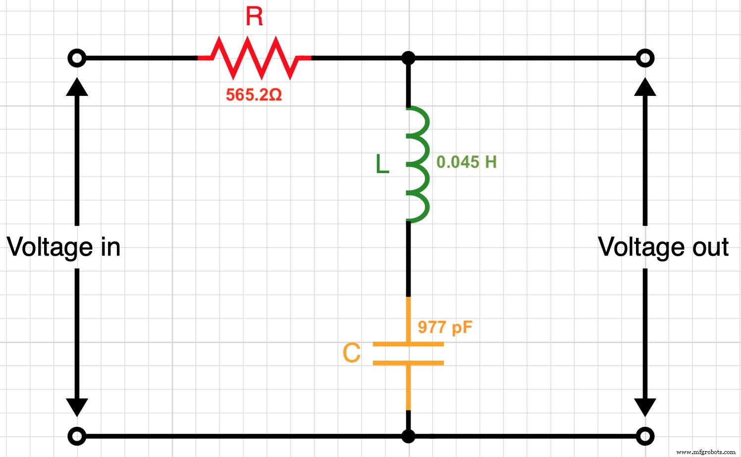
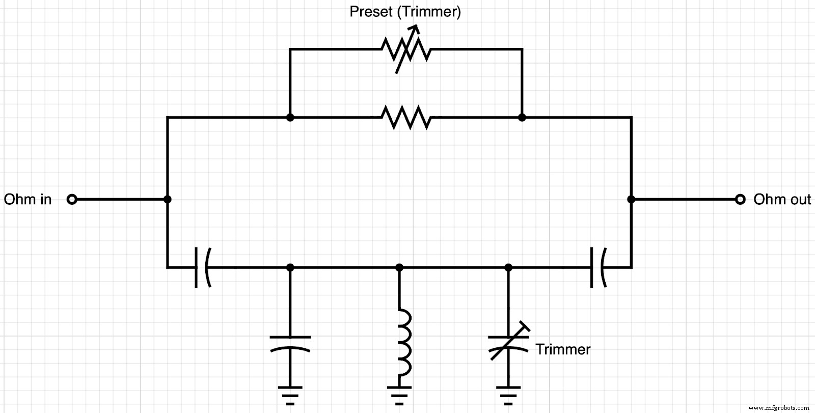
An RLC notch filter for 23 kHz and 25 kHz cut-off frequencies
Notch Filter Transfer Function
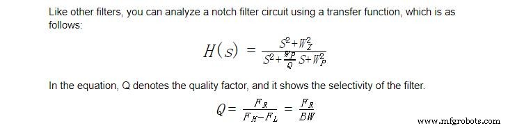
BW is the bandwidth.
WZ is the zero circular frequency (cut-off frequency), while WP is the pole circular frequency. WP determines the type/ characteristics of the filter, and there are three possibilities.
- If the pole circular frequency is higher than the zero circular frequency (WP>WZ), then it is a high pass notch filter
- If the pole circular frequency is lower than the zero circular frequency (WP<WZ), then it is a low pass notch filter
- However, if the two are equal, then you have a standard notch filter
Therefore, you can rewrite the formula of a standard notch filter as:

WC is the width of the rejected band, while W0 is the rejected frequency (central).
Notch Filter Applications
- Communication systems: There is a high probability of message signal interference by harmonic noises (especially by power lines), and notch filters help to remove this range of frequencies.
- Audio applications (Acoustic applications): Humming noises can distort or create sharp spikes in audio engineering devices like amplifiers and PA systems, but notch filters can eliminate these frequencies.
- Medical engineering: Power line interference can mess with EEG and ECG readings. Notch filters help to eliminate this powerline noise from the biomedical signals.
- Internet services: Internet transmission over telephone lines, such as DSL, is susceptible to unwanted interference, and the only way to deal with it is a notch filter as a line noise reducer.
- Digital signal and image processing
- Optical applications
Summary
Notch filters are handy devices in several applications, primarily because they can block interference caused by AC power sources.
If you want to build this device, the information above and circuit diagrams are enough to guide you through the process.
However, you need to buy the required discrete components for that project first, and we have everything you need. Contact us to get affordable deals on authentic PCBs, resistors, capacitors, and all the parts required to set up the filter.
Industrial Technology
- E3.cable: Comprehensive Cable Design Software for Optimized Electrical Harnesses
- Optimize Wiring Harness Design with ECAD: Quality, Speed, and Cost Efficiency
- Essential RF & Microwave Design Principles for Reliable PCB Performance
- High‑Voltage PCB Design: Materials, Safety, and Best Practices
- Optimizing PCB Design for Manufacturing: Key Strategies & Best Practices
- Top 5 Design Strategies for Successful Reaction Injection Molding (RIM)
- Proven Design Strategies for Cast Molding with Thermoset Polyurethanes
- 4 Ways Drawing Approvals Enhance Protocase Order Accuracy
- 10 Essential Tips for Designing Low‑Noise Amplifiers
- Mastering Tolerance Design: Key Strategies for Precision and Cost Efficiency