


Understanding Negative Edge Triggered Flip-Flops: Core Electronics Insight
Flip-flops or latch circuits majorly help to design registers and counters that store data in a multi-bit number form. However, the register devices often need many flip-flops circuits connected sequentially to each other. The sequential circuits must then go through triggering processes for effective operation.
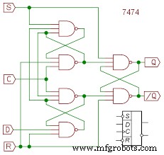
A flip-flop circuit
Source: Wikipedia
Triggering a flip flop involves changing the input signal using a trigger pulse or clock pulse. In turn, the flip-flop output will also change.
There are several ways to trigger a flip-flop, such as high-level, low-level, and others. We’ll expound on negative edge triggering, then touch on the other methods.
- Edge-Triggered Flip-Flops
Before we proceed, let us go through some crucial terms;
Flip-flop: We use flip-flops instead of latch circuits after activating a multivibrator circuit at the transitional edge of its square wave.
Clock signal: It is the enabling signal.
Edge-triggered S-R circuit: Preferably termed as S-R flip flop.
Edge-triggered D circuit: preferably D flip flops.
D, J-K, and S-R inputs are collectively synchronous inputs. Additionally, they all appear in positive edge-triggered and negative-edge-triggered flip-flops. The synchronicity is because you can transfer data inputs to the flip-flop’s output at the triggering edge of a clock pulse.
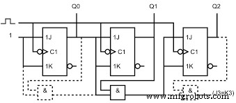
A synchronizing input counters
Source: Wikipedia
Asynchronous inputs (that are clear (CLR) and direct set (SET)) change the flip-flop’s state without clock pulses.
Positive edge-triggered (raising edge)
S-R, J-K, and D inputs here mean no bubble at the clock input.
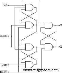
Delay flip-flop
It has three SR NAND latches, and it holds the output till the clock pulse finishes changing the digital signal from low to high. Further, the input stage comprises two latches, while the output stage only has one latch. Also, the input stage has the data input connected to a single NAND latch.

Edge-triggered D flip-flop
Source: Wikipedia
S-R flip-flop
Here, the output changes regarding the input at the +ve edge of the clock pulse. The S and R inputs won’t affect the output if you don’t have a trailing advantage on the clock pulse. But, at the clock’s positive/leading edge, the flip flop circuit is active and follows R and S input changes.
Changes in one clock cycle include;
- High S and low R = high output at the leading edge/ SET flip flop.
- Low S and high R = low output at the leading edge/ RESET flip flop.
- Low S and R = No change at the positive clock pulse
- High S and R = Unacceptable state.
S-R flip flop circuit in positive triggering
J-K flip flop
An edge-triggered J-K flip flop works similarly to an S-R flip flop. However, if both S and K states are high, there’s an output toggling. The creation adopts an opposite form at the leading edge of the clock pulse.
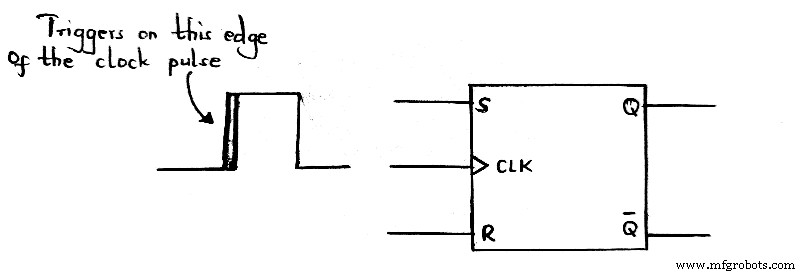
Negative edge-triggering (falling edge)
Negative edge-triggering circuit
The three inputs in negative edge-triggered flip-flop circuits imply that there’s a bubble at the clock input.
Edge-triggered S-R flip-flop
The truth table and operation of a negative edge-triggered device are similar to positive triggering. The only difference is, for negative triggering, the falling edge of the trigger pulse is the trailing edge.
You can change S and R inputs anytime if you have a HIGH or LOW clock input without disrupting the output. An exception to the rule is when there’s a short period around the clock’s triggering transition.
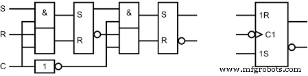
Edge-triggered S-R circuit
Source: Wikipedia
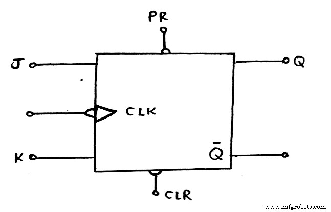
Edge-triggered J-K flip-flop
A J-K flip-flop works the same way as an S-R flip-flop. However, the J-K flip-flop circuit lacks an invalid state. Then, when you have both K and J inputs at a high state, the outputs switch to an opposite state (toggling).
Edge-triggered D (delay/data) flip-flop
A D flip-flop has a simple operation, and that is because it only has a single input addition to its negative clock pulse. It’s often recommendable when you need to store a single data bit (i.e., 0 or 1).
When there is a HIGH D input after applying a clock pulse, the flip-flop automatically SETs, then stores a 1. Conversely, when there’s a LOW D input after applying clock pulse, the flip flop circuit RESETs then holds a 0.
Edge-triggered D flip flop circuit
Source: Wikipedia
- Why do we use negative edge triggering?
Negative edge triggering is preferable because it only discharges operations, contributing to more power saving. Contrarily, a positive edge triggering will only charge the capacitance.
Furthermore, you can avoid glitches occurring because of race conditions when using a negative-edge triggered flip-flop. The most common example of glitch reduction is in the digital application of flip-flops in Field-Programmable Gate Array (FPGA) circuits. You can additionally use a master-slave flip-flop to avoid racing during the clock period.
3. Principle of Clock Pulse Transition
A clock pulse edge always moves from 0 to 1, then 1 to 0 when you have a signal. Therefore, a single call will result in two transitions.
0 to 1 movement is the positive transition whereas, 1 to 0 denotes a negative change. A positive logic operation with a low to high growth is the leading edge of the clock signal. On the other hand, a high to low growth is the clock trailing edge.
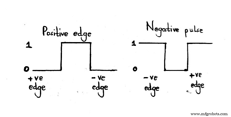
Types of clock pulse transition
Sometimes, you can experience multi-transition challenges in the flip-flops that destabilize the digital circuits. Eradicating the problem involves making the flip-flops respond to negative and positive edge transitions only, not an entire pulse duration.
4. Flip flop – Other Triggering Methods
High-level triggering
Generally, apply the high-level triggering method when you require the flip flop to respond in its high state. You can identify the state in a straight lead from the input of the clock.
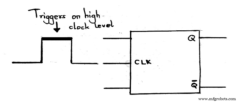
High-level triggering
Negative Edge Triggered: Low-level triggering
Contrarily, low-level triggering is applicable in low-state flip-flops. Also, apart from checking the clock input lead, you can examine a low state indicator bubble.
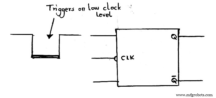
Low-level triggering
Negative Edge Triggered:Positive edge triggering
A positive edge trigger ensures the flip flow responds to a state of low to high transition. You can use a triangle alongside a clock input to identify the positive triggering.
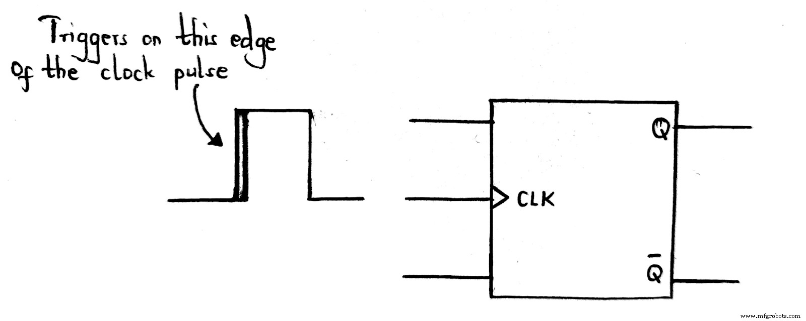
Positive edge triggering
Summary
To sum it up, edge triggering minimizes the transient and noise effects in electronic circuits while triggering the input. Moreover, the triggering allows devices to produce a smooth trigger that is much faster than external feedback loops. The devices will thus swiftly accept inputs, then accurately close off the entrance before changing the output and input values.
The text above gives details on the types of clocked flip-flops you might encounter. They all work differently to change the output through the input. And so, do reach out to us. We’We’reowever, still open for inquiries on edge-triggering.
Industrial Technology
- Polymer Consumables ODM: A Comprehensive Guide to Design and Innovation
- Mastering Laser Cutting of Steel: Fundamentals and Machine Selection Guide
- Choosing the Right CNC Router Bits: Selection Tips & Operational Precautions
- Everything You Need to Know Before Buying an Edge Banding Machine
- Sheet Metal Fabrication 101: Mastering the Basics of Metal Sheet Production
- 15 Essential Electronic Circuit Board Components You Must Know
- 5 Essential Insights into the MSP430 Microcontroller
- Essential CNC Milling Basics: Mastering Contour & Profile Machining
- Essential Fundamentals of Engineering Drawings
- 42 Essential Principles of Mechanical Drawing: A Comprehensive Guide