


NodeMCU Pinout Guide: Essential Connections for IoT Development
NodeMCU
Are you confused about the pinout details of a NodeMCU pinou ? Do you want to know more about NodeMCU for your IoT projects? Then you’re in the right place.
The NodeMCU name combines “node” and “micro-controller unit.” Plus, it refers to the firmware, not development kits. So if you’re using NodeMCU with Arduino, you might think both the node and micro-controller unit is the same. But there are differences, especially at the pinout.
Not to worry, we’ll help you understand these differences better in this article.
You’ll also learn everything about the NodeMCU, its development kits, and how to add them to your circuits.
Brief About NodeMCU ESP8266
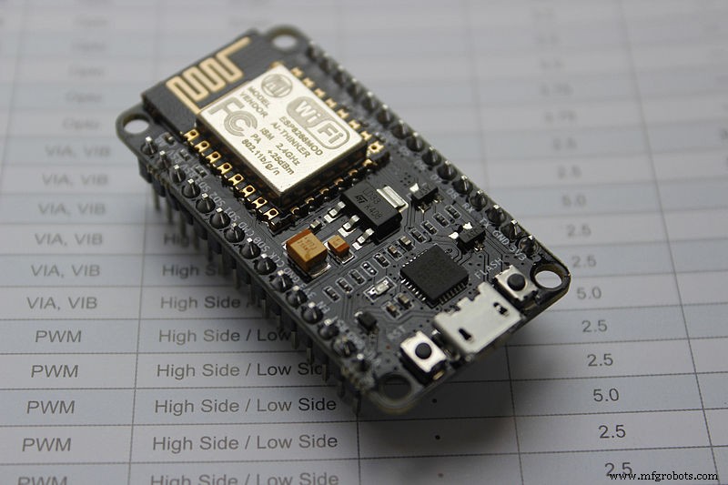
NodeMCU ESP8266
NodeMCU is a development and open-source chipset that provides a platform for prototype designs with open-source functionality. You can also use the firmware to prototype IoT projects that run Lua code lines.
Also, the Espressif system’s Wi-Fi Soc (ESP8266 ) gives the NodeMCU a platform to operate. Hence, its hardware operates smoothly on the platform of ESP-12.
Interestingly, the NodeMCU ESP8266 is the development kit for the NodeMCU firmware. It features the ESP-12E module that comes with an ESP8266 chip.
But that’s not all. The ESP8266 chip also features a “Tensilica Xtensa 32-bit LX106 RISC microprocessor.” Hence, it has RTOS supports and runs at a modifiable clock frequency of 80MHz to 160MHz.
With the NodeMCU, you can get 4 MB and 128 kilobytes of RAM and flash memory for storing programs and data.
Moreover, the NodeMCU’s high processing power and built-in features ( deep sleep, BlueTooth, and Wi-Fi) make it perfect for IoT projects.
Also, you can power the NodeMCU development board with the exterior supply pin (VIN pin) and a micro USB jack. You can also use I2C, UART, and SPI interfaces with the NodeMCU.
NodeMCU Development Board Pinout
Here’s the pinout configuration for the NodeMCU development board:
NodeMCU ESP8266 Specifications and Features
Here are the features and specifications of the NodeMCU ESP8266:
- 32-bit Microcontroller
- 3.3V operating voltage
- 7-12V input voltage
- Digital I/O Pins (DIO): 16.
- Analog Input Pins (ADC): 1.
- 2 UARTs
- 4 SPIs
- 1 I2C
- 4 MB memory (flash)
- 64 KB SRAM
- Modifiable clock speed of 80 – 160 MHz
- PCB Antenna.
- It has a small size that can fit in your pockets easily.
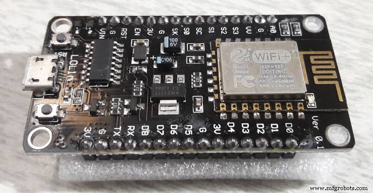
ESP8266 NodeMCU Breakout Board
While the ESP-12E module serves as a baseboard, the NodeMCU team developed a NodeMCU breakout board. The breakout board is exclusively for their NodeMCU firmware, and it’s also open-source.
Now let’s look at the pinout diagram and pin details of the breakout board:
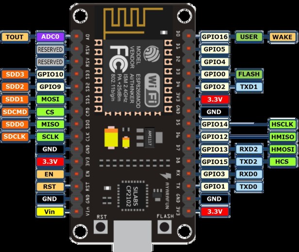
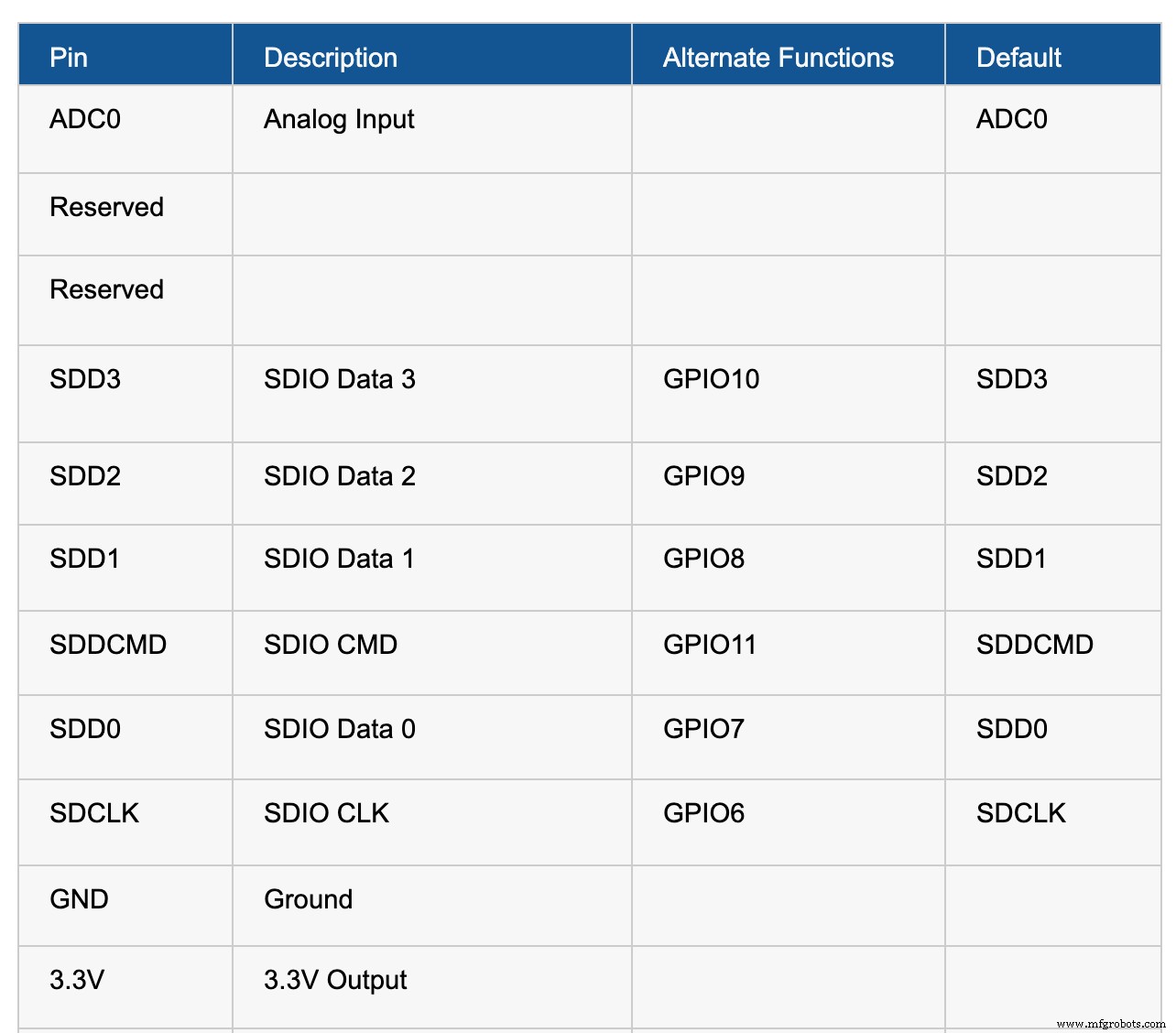
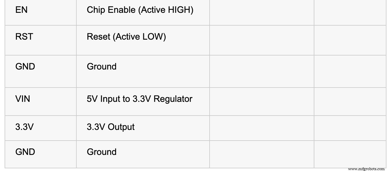
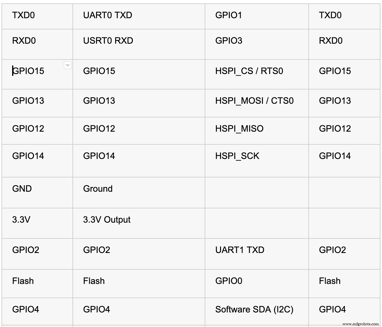
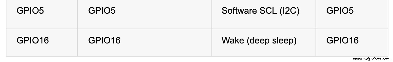
NodeMCU Pinout Diagram
The NodeMCU breakout board has thirty pins. Eight out of these pins handle power, while two are reserve pins. The other twenty pins work with ESP-12E module pins.
Screenshots for the table of pins:
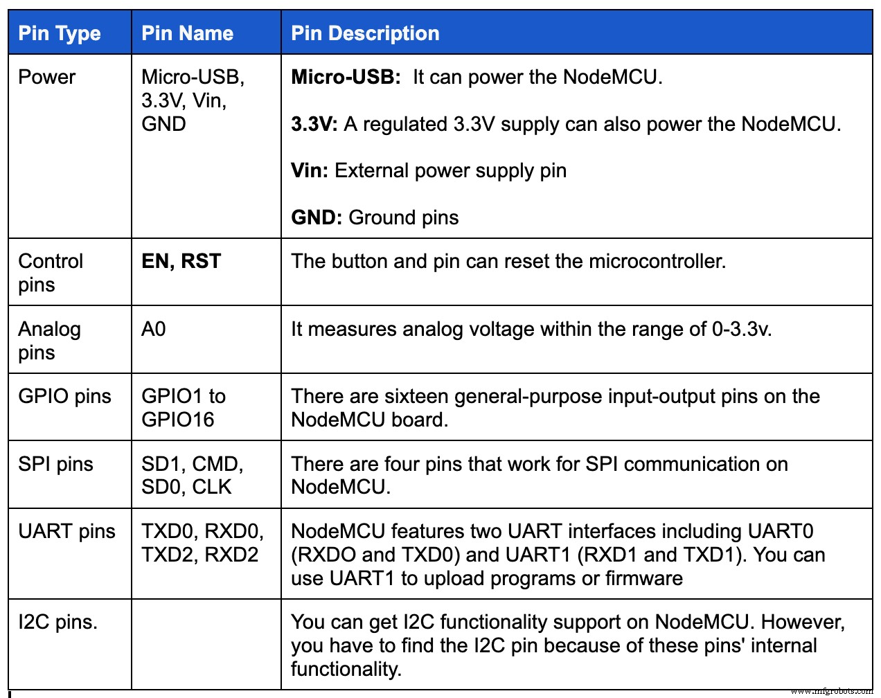
Power, Peripherals, and Pins
Powering the NodeMCU
As we mentioned earlier, you can use two methods to power the NodeMCU board: a micro-USB port or Vin pin. The ESP8266EX is also compatible with 3.3V. Hence, the NodeMCU board features an AMS1117-3.3v regulator IC.
Plus, you can apply a regulated 5v power to the Vin pin. Also, there are three 3.3V pins that you can connect to the regulator’s 3.3v output.
Available NodeMCU Peripherals
Here are all the available peripherals on the NodeMCU ESP8266EX SoC:
GPIO Pins
The NodeMCU ESP8266EX has up to seventeen GPIO pins. However, you can’t use all of them because some already work for their alternate functions. These alternative functions include SDIO, UART, and SPI.
UART.
UART
There are two hardware UARTs on the ESP8266EX, including the UART0 and UART1. Both UART hardware have baud rates of up to 115200.
Also, you can use UART0 for data control flow and communication. In contrast, UART1 works for data logging and uses only the TX pin–while the SDD1 uses its RX pin. Check out the table below to find out what GPIO pin each UART uses:
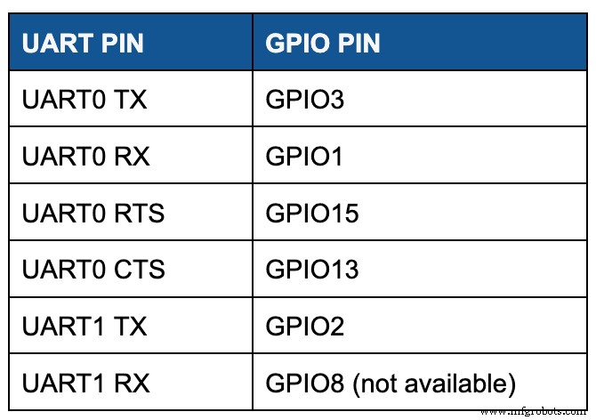
Screenshots of the UART pin in a tabular form
I2C
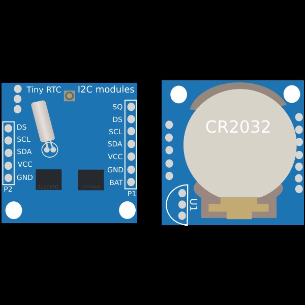
I2C Modules
There’s no I2C hardware on the ESP8266, but you can implement it via software. Also, you can use GPIO4 and GPIO 5 as SDA and SCL pins since these pins do not have alternative functions.
SPI

SPI
You can find two SPI interfaces on the ESP8266EX SoC, including SPI and HSPI. In addition, both interfaces support Master and Slave operations. Also, you can configure the master clock mode to 80 MHz while the slave clock mode runs at 20 MHz.
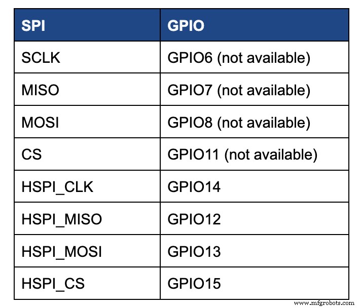
Screenshot showing the different GPIO pin numbers
Note: you’ll find that there’s a multiplex of GPIO pins for SPI with few SDIO pins. Plus, SPI helps connect the 4 MB SPI flash on the ESP-12E. Hence, you can’t access the SPI pins. You can only use HSP pins for SPI communication.
Extra Features
You can use interrupt functions on all GPIO pins except GPIO16. Also, there are two LEDs on the breakout board. One connects to the GPIO2 on the ESP-12E module, while the other connects to GPIO16 on the NodeMCU board.
Using ESP8266 NodeMCU with Arduino IDE
If you want to use the ESP8266 NodeMCU with Arduino IDE, you first have to add it to the software. Luckily it’s easy to do this. First, copy the code URL and follow the following steps:
- Step 1: Open your Arduino IDE software and navigate to preference in your file menu. Then, input the code URL you copied in ‘Additional Board Manager URLs.”
- Step 2: Navigate to Tools menu> Boards>Boards manager and search for ESP8266. Install the available ESP8266 boards, and you should see the “INSTALLED” label.
You should see boards based on ESP8266 like the NodeMCU on your Arduino IDE. Afterward, you can choose your preferred board from the list to upload your code.
Other Espressif Boards and Other Development Boards
Here are the available Espressif boards and development boards alternatives:
- ESP8266
- ESP12E
- ESP32
Development Boards:
- Arduino
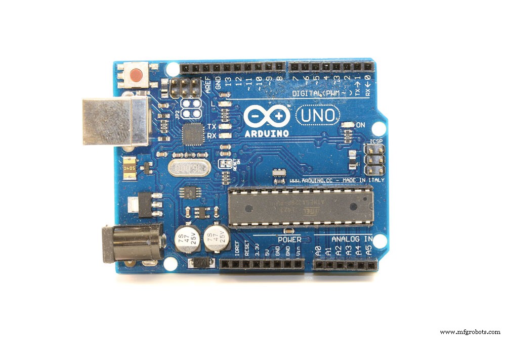
Arduino
- Raspberry Pi
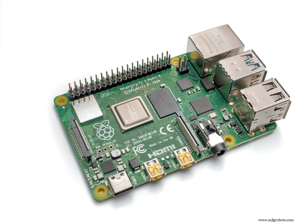
Raspberry Pi
- PIC Development Board
- AVR Development Board
- MSP430 Launchpad
- Intel Edison
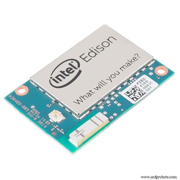
Intel Edison
- Beagle Bone
Applications
- IoT device prototyping
- Works for applications that require low power battery operations
- Network projects
- Useful for applications that require multiple I/O interfaces with Wi-Fi and Bluetooth functionalities
Final Words
NodeMCU
NodeMCU is an excellent open-source and programmable firmware that’s great for various IoT applications. The NodeMCU pinout is also simple, budget-friendly, smart, and comes with Wi-Fi to put the icing on the cake.
Hence, you can also reduce the stress of configuring hardware with NodeMCU’s advanced API for hardware IO. The full development kit integrates with PWM, IIC, GPIO, 1-Wire, and ADC on one board.
So, if you have any questions, feel free to contact us, and we’ll be happy to help.
Industrial Technology
- Pick & Place Robot Arms: A Complete Guide to Automation and Productivity
- Everything You Need to Know About USB‑C: Features, Pinouts & Power Delivery
- Explore the Top Raspberry Pi 4 Projects of 2020
- Mastering LED Wiring: 8 Essential Tips for Parallel Circuits
- LED Flasher Module Guide: Everything You Need to Know
- Understanding Transformers: Key Principles & Practical Applications
- Flame Sensor Essentials: Install, Maintain, and Maximize Safety
- Choosing Between I2C and SPI: Key Differences Explained
- Mastering Microcircuit Boards: Essential Design Tips & Tricks
- Essential Waterjet Terminology for Professionals