


Choosing Between I2C and SPI: Key Differences Explained
Are you designing a project, and it’s crucial to choose between I2C vs. SPI? But you don’t know which one to pick? If yes, we’ll help you decide which one is better for your project.
First off, the I2C and SPI are “low-end” protocols. But they are easy to use and work perfectly for communication between chips on your PCB.
However, selecting the wrong protocol for your project can result in undesirable results. Nevertheless, we’re here to help you understand the difference between these two similar protocols.
Are you ready? Let’s begin!
What is an SPI Protocol?
In the 1980s, Motorola developed the SPI protocol to establish communication between the microcontrollers of that time with other peripherals like EEPROM.

EEPROM
So, the SPI protocol utilizes four signal lines for communication between parts. However, it’s crucial to note that these don’t include the ground and power lines. Here are the four active signal lines:
- SS: Slave Select line (controlled by the master SPI)
- MOSI: Master Out Slave In (controlled by the master SPI)
- SCLK: Serial Clock (controlled by the master SPI)
- MISO: Master In Slave Out (controlled by the master SPI device)
On this note, the four lines allow a master SPI (controlling device) to communicate with a slave SPI (peripheral device).
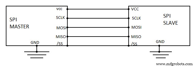
SPI Protocol Interface
Moreover, you can only have one controller device on an SPI bus. But, there is no limit to the number of peripherals you can add. Also, adding more peripherals means increasing the SS lines. Hence, here is an illustration of how you can use three separate SS lines to control different peripherals.
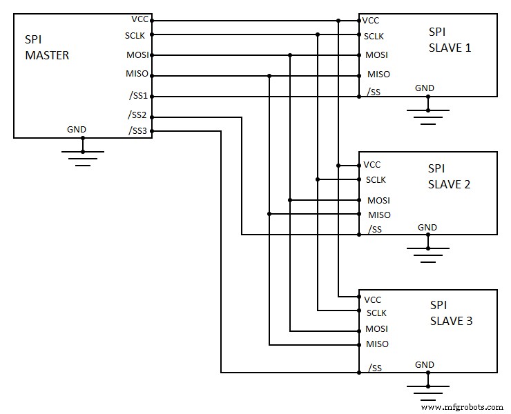
SPI Protocol Interface With Multiple enslaved people
Furthermore, when the master SPI wants to communicate with the peripherals by either sending or receiving data, it pulls the matching SS line. Consequently, the line will be below. Hence, the SCLK line activates and is high and low at a set frequency.
Additionally, the master SPI uses the MISO line to send out data and samples simultaneously. Also, keep in mind that there can only be communication between one peripheral and the master SPI at a time.
What is an I2C
Alternatively, in 1982, Philips Semiconductors (now NXP Semiconductors) developed the first I2C protocol to systematize communications between chips on one PCB.
Unlike its SCI counterpart, the I2C protocol has two communication lines–excluding the ground and power lines. These lines include:
- SDA: Serial Data line
- SCL: Serial Clock line
So, you can attach any number of enslaver and agent devices to one bus. Also, you must keep both the SCL and SDA lines as open-drain lines. As a result, your devices will only have one low line at a time. In addition, you’ll need a pull-up resistor on your pipes. That way, you can pull your line back to high.
I2C Protocol Interface
Due to the open-drain design of the I2C protocol, you can use multiple masters on the same bus. But if two controller devices start communicating simultaneously, there will be an arbitration that causes one of the devices to stop transmitting.
Meanwhile, the controller devices monitor the SDA line while communication occurs. So, if one device detects that the SDA line is low while transmitting, it will stop sending. And this allows another controller device to communicate.
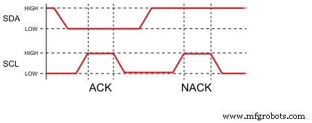
Also, the controller I2C device will transmit a START condition to initiate communication. Consequently, the SDA line will be low while the SCL line remains high.
Then, the controller device will transmit a 7-bit address of the recipient it wants to send to and a read bit (1) or write bit (0). At this point, a device on the bus will only respond if it has a matching 7-bit rate address by making the SDA line low.
Differences Between the I2C and SPI
Both the SPI and I2C are similar because they are both “low-end” protocols. Additionally, both protocols lack the speed and other features boasted by their heavy-weight cousins (SATA, Ethernet, USB, and others).
But when it comes to the working principles and features. Let’s take a closer look at the differences between the two protocols.
USB Connector
First off, you can set four different modes on the SPI protocol to determine how the clockworks. And for the communication to work, the enslaver and agent devices must use the same model.
- Mode 0: data sampled on a rising clock edge, clock idles low
- Mode 1: data sampled on falling clock edge, clock idles low
- TMode 2: data sampled on falling clock edge, clock idles high
- Mode 3: data sampled on a rising clock edge, clock idles high
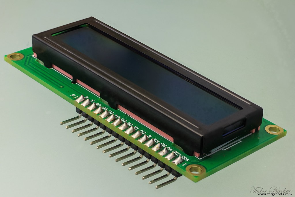
In addition, SPI data transfer speeds can go beyond 10 Mbps, making it perfect for transferring vast amounts of data. Also, you can find SPI protocols on sensors with fast update rates like LCDs and accelerometers.
LCD
Alternatively, the I2C can only send data in the one-byte packet at a time. Plus, the receiving peripheral must acknowledge each byte with an ACK bit. Additionally, the I2C protocol has three modes with different data transfer speeds.
ACK Bit
The standard model reaches a maximum of 100 kbps, fast mode caps at 400 kbps, and the high-speed mode maxes out at 3.4 Mbps. Hence, the I2C protocol is significantly slower than the SPI protocol. As a result, I2C protocols work best in temperature sensors and analog-to-digital converters.
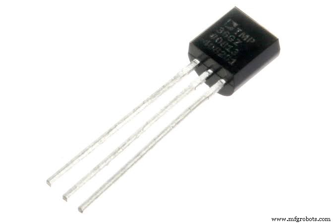
Temperature Sensors
Comparing I2C and SPI
The table below further shows the significant differences between the I2C and SPI:
| Feature | SPI | I2C |
| Pin drive | Push-pull mode | Open-drain mode |
| Max. Speed | None (But you can find 10 – 100 Mbps) | 100 kbps (standard method)400 kbps (fast way)3.4 Mbps (high-speed mode) |
| Multi-master | No | Yes |
| Signal lines | 4 (extra devices adds extra lines) | 2 |
| No. of Peripherals | The number of pins available for SS lines on the master SPI is the only limit to the number of peripherals you can have | Max. of 112 with 7-bit addressing |
| Flow control | No | Yes |
SPI vs I2C Protocols – Pros and Cons
SPI
Pros
- The SPI protocols consume a small amount of power
- It also supports high-speed full-duplex communications
Cons
- There are different versions and customized variants that cause compatibility issues
- You need extra signal lines to communicate with multiple peripherals on the same bus
- Only supports short-distance communications. You can’t transfer data to devices on separate boards
I2C
Pros
- You don’t need additional lines to control multiple devices on the same bus
- Can transmit data to other PCBs but with low transmission speeds
- Has a lower noise sensitivity
- Can transmit data over longer distances
- Less expensive to use than SPI
Cons
- Transfer speeds are slower than SPI
- Uses more power than the SPI protocol
- The failure of one device to release the communication bus can lock up the I2C protocol
Factors You Should Consider When Choosing Between SPI and I2C
Selecting the best protocol for your project goes beyond the price tag. So, here are a few things to consider before making your choice:
Limited Pins
Here are the advantages and disadvantages of both SPI and I2C protocols: if you don’t enjoy using microcontrollers with more than 100 pins, this is a crucial factor to consider. In this case, you should opt for a protocol that requires lesser lines for communications.
Power
Depending on your design, you might want to minimize or maximize power consumption. So, you have to ensure that you choose a protocol that best suits your consumption needs.
Speed
When it comes to transferring data in enormous amounts, every microsecond is crucial. So, if speed is what you need, go for a protocol that meets your speed standards.
PCB Size
It’s vital to consider the size of your PCB before choosing any protocol. Consequently, you’ll boost your chances of getting desirable results.
Choosing Between SPI and I2C
Here are the features of each protocol to help you make the best decision for your design:
| Features | SPI | I2C |
| Speed | If your design requires higher-speed transmissions, the SPI protocol is the best choice. | You can choose I2C for designs for low-speed devices |
| PCB size | If you’re not bothered about the size of your PCB, you can’t go wrong with either SPI or I2C. | If your PCB has a smaller size and fewer tracks, consider choosing the I2C |
| Limited Pins | Go for the SPI protocol if you don’t mind adding extra lines for communication. | If you’re not comfortable with many tracks, then I2C is an ideal choice. |
| Power | For lower power consumption devices, use the SPI protocol | For higher power consumption devices, use the I2C protocol |
Understanding UART
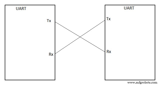
UARTs are physical circuits in an integrated or microcontroller that establish serial communication between devices in embedded systems.
Also, when you’re dealing with UART communication, there’s always direct communication between the UART transmitter and UART receiver.
UART vs I2C vs SPI
In contrast with other communication protocols like SPI and I2C, the UART is purely physical. Plus, it doesn’t use a master/slave paradigm to communicate. Instead, the microcontroller uses two UART devices to send and receive data. Additionally, you only need two wires for UART communication. And the cables will help transmit data from the transmitter’s Tx pin to the receiver’s Rx pin.
UART Protocol Interface
Rounding Up
In reality, the SPI and I2C protocols are used in various applications. Sometimes, you might find yourself with devices that feature SPI and I2C interfaces on one chip. So, you don’t have to choose between the two.
However, if you need to choose between the two protocols, the SPI is better for projects that need faster transfer speeds. On the other hand, if your microcontroller has limited pins, the I2C protocol would work better.
Have any questions? Feel free to contact us. We’ll be more than happy to help.
Industrial Technology
- Protect Your Motors: The Essential Benefits of Line Reactors
- Explore the Top Raspberry Pi 4 Projects of 2020
- Mastering LED Wiring: 8 Essential Tips for Parallel Circuits
- LED Flasher Module Guide: Everything You Need to Know
- Understanding Transformers: Key Principles & Practical Applications
- Public vs. Private Cloud: Key Differences Every IT Professional Should Understand
- Essential Waterjet Terminology for Professionals
- 5 Key Insights on Silicone Rubber Molds You Must Know
- Knurling Explained: Mastering Textured Finishing Techniques
- Cooling Towers Explained: Function, Importance, and Industry Applications