


Installing Dual-Function Smart AFCI/GFCI Breakers in a 120/240V Smart Load Center
Installing Dual-Function Smart AFCI/GFCI Breakers in a 120/240V Smart Load Center
What Is a Dual-Function AFCI/GFCI Breaker?
A dual-function AFCI/GFCI breaker merges Arc‑Fault Circuit‑Interrupter (AFCI) and Ground‑Fault Circuit‑Interrupter (GFCI) protection into a single device. Installed in the service panel, it safeguards the entire branch circuit—from the breaker to the final outlet—meeting the safety mandates of the National Electrical Code (NEC).
The AFCI portion detects hazardous arcing caused by loose connections, damaged conductors, or deteriorated insulation. When an abnormal arcing signature is identified, the breaker trips, interrupting the circuit and mitigating fire risk.
The GFCI portion monitors the balance of current between the hot and neutral conductors. An imbalance of approximately 5 milliamps, indicative of leakage to ground, triggers an almost instantaneous trip to protect people from electric shock. By integrating both technologies, a dual‑function breaker delivers comprehensive protection against fire and shock hazards on a single circuit.
Code Requirements
NEC 210.8 requires GFCI protection, while NEC 210.12 mandates AFCI protection in bedrooms, kitchens, laundry rooms, and similar locations. When a branch circuit needs both types of protection, a dual‑function breaker is typically the most efficient solution, eliminating the need for separate devices.
For dwelling units, a circuit that serves a GFCI‑required location within an AFCI zone must have both protections. All 120V, 15A & 20A receptacle circuits serving kitchen countertops, for example, require dual protection. An electrician can install either an AFCI breaker with a GFCI receptacle or a dual‑function breaker to satisfy NEC 210.8 and 210.12.
Good to Know: A combo AFCI/GFCI breaker satisfies both NEC 210.12 (AFCI) and NEC 210.8 (GFCI) in one device, simplifying compliance.
Smart AFCI/GFCI Breakers
Leviton offers second‑generation smart AFCI/GFCI breakers (e.g., LB115-DST for 15A and LB120-DST for 20A) that support remote control via the My Leviton app. These breakers feature a short‑circuit current rating of 10 kA and allow you to turn the breaker ON/OFF, schedule operation, and review operational history—all from your smartphone.
Good to Know: Smart AFCI/GFCI breakers require a Leviton load center (such as LP220-BPD) and either an LDATA Hub or a Whole‑Home Energy Monitor (LWHEM) for full smart functionality.
Wiring a Dual-Function Smart AFCI/GFCI Breaker
Installing the Breaker
- Switch OFF the main breaker in the panel or upstream disconnect. Verify power is OFF with a non‑contact tester.
- Remove the panel cover to access the breaker bays. A 1‑pole breaker occupies one slot and snaps over a single busbar.
- Position the breaker handle in the OFF position and snap the breaker onto the busbar.
- Tighten all terminal screws to 25 in.‑lbs (or follow the torque value on the device’s back panel).
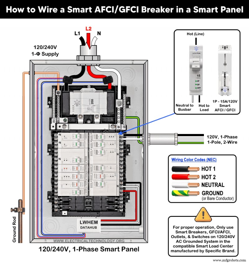
Connecting Load Conductors
Second‑generation smart AFCI/GFCI breakers are available only as 1‑pole units rated at 15A or 20A. Wiring is straightforward:
- Strip approximately 0.4 inch (≈10 mm) of insulation from the load conductors.
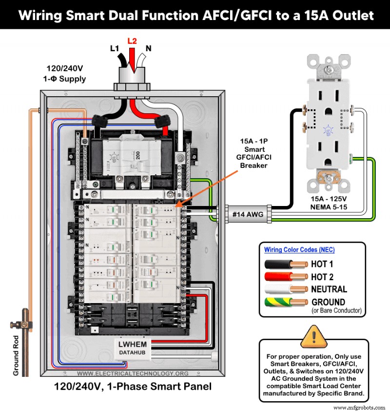
- Connect the hot (black) conductor to the brass screw on the breaker.
- Connect the neutral (white) conductor to the silver screw on the breaker.
- Bond the ground (bare or green) to the panel’s grounding busbar.
Warning: The load neutral must be attached to the breaker’s neutral terminal (marked "N"), not to the panel’s neutral busbar. The ground conductor must bond to the panel’s grounding bus, not to the breaker.
The wiring diagram below illustrates a 1‑pole, 120V smart AFCI/GFCI breaker wired with #14 AWG conductors to protect a 15A/120V outlet (NEMA 5-15).
Replace the panel cover, ensuring labels and handles remain visible. Restore power at the main breaker and set the smart AFCI/GFCI breaker to ON. If the breaker fails to stay ON or trips immediately, double‑check neutral and load connections. Refer to the LED status indicator troubleshooting table below for guidance.
Testing the Breaker
After restoring panel power, move the breaker handle from OFF to ON.
- If the breaker remains ON and the handle window lights green, the wiring is correct and the breaker is operational.
- If the breaker does not reset, re‑inspect wiring, consult the LED status indicator table, or contact a licensed electrician.
LED Status Indicator Troubleshooting Table
The following table explains the diagnostic meaning of each LED state on a smart AFCI/GFCI breaker.
| Breaker Handle | AF LED | GF LED | ON/OFF LED | Device Status |
|---|---|---|---|---|
| Green | OFF | OFF | OFF | ON |
| Green | OFF | OFF | ON – Solid | Remote OFF |
| Red | OFF | OFF | OFF | Short‑circuit / Overload Trip |
| Red | ON – Solid | OFF | OFF | Series Arc Fault Trip |
| Red | OFF | ON – Solid | OFF | Ground Fault Trip |
| Red | ON – Blinking | OFF | OFF | 1 Sec. Delay – Parallel Arc Fault Trip |
| Red | OFF | ON – Blinking | OFF | 3 Sec. Delay – Neutral Miswired |
| Red | ON – Blinking | ON – Blinking | OFF | 0.1 Sec. Delay – Replace Breaker |
| White | OFF | OFF | OFF | Manual OFF |
Precautions
- Always disconnect the power by switching OFF the main breaker before any electrical work.
- Avoid installing AFCI, GFCI, AFCI/GFCI, or GFPE breakers on circuits with shared neutrals; such setups can cause nuisance tripping.
- Do not use AFCI/GFCI breakers for life‑support equipment in hospitals or health‑service units—unnecessary tripping can interrupt critical power.
- Install GFCI/AFCI breakers using only copper or copper‑clad conductors.
- If you are unsure about any step, consult a licensed electrician to ensure compliance with local codes.
- Exercise extreme caution when working with electricity; improper handling can cause injury, property damage, or death.
- The author assumes no liability for any loss, injury, or damage resulting from the use or misinterpretation of this information or from improper installation of any circuit.
Resources
Smart Devices Wiring Series
- How to Wire 120/240V Smart Load Center with Smart Breakers
- How to Wire a Smart Breaker in a Smart 120/240V Panel
- How to Wire a Smart GFCI Breaker in a 120/240V Smart Panel
Main Panels Wiring Tutorials
- How to Wire 120/240V Main Panel – Breaker Box Installation
- How to Wire 120V/208V, 1-Phase & 3-Phase Main Panel?
- How to Wire 120/208/240V High Leg Delta 1-Phase & 3-Phase Main Panel?
- How to Wire 277/480V, 1-Phase & 3-Phase Main Service Panel?
- How to Wire 347/600V, 1 and 3-Phase Main Service Panel?
- How to Wire a Subpanel? Main Lug Installation for 120V/240V
- How to Wire a Spa Panel Box for a Hot Tub using 2P GFCI & Breaker
- Single Phase Electrical Wiring Installation in Home – NEC & IEC
- Three Phase Electrical Wiring Installation in Home – NEC & IEC
- How To Wire a Single Phase kWh Meter – 120V/240V
- How to Wire a Three-Phase Meter? 120/208/240/277/347/480/600V
Wiring Smart / Standard GFCI & Breakers
- How to Wire a 1-Pole Breaker
- How to Wire a 2-Pole Breaker
- How to Wire a 3-Pole Breaker
- How to Wire a 1-Pole GFCI
- How to Wire a 2-Pole GFCI
- How to Wire a 3-Phase, 3-Pole GFCI
- How to Wire a Tandem Breaker
- How to Wire GFCI Circuit Breakers
- How to Wire an AFCI Breaker
Wiring Smart / General Outlets & GFCI/AFCI Receptacles
- How to Wire an Outlet Receptacle? Socket Outlet Wiring Diagrams
- How to wire a GFCI Outlet?
- How to a Wire 3-Way Combination Switch and Grounded Outlet?
- How to Wire a 15A – 125V Outlet – NEMA "5-15" Receptacle
- How to Wire a 20A – 125V Outlet – NEMA "5-20" Receptacle
- How to Wire a 15A – 250V Outlet – NEMA "6-15" Receptacle
- How to Wire a 20A – 250V Outlet – NEMA "6-20" Receptacle
- How to Wire a 50A – 125/250V Outlet – NEMA "14-50" Receptacle
Switches Wiring
- How to Wire Single Pole, Single Throw (SPST) as 2-Way Switch?
- How to Wire Single Pole, Double Throw (SPDT) as 3-Way Switch?
- How to Wire Double Pole, Single Throw Switch? Wiring DPST
- How to Wire Double Pole, Double Throw Switch? Wiring DPDT
- How to Wire Double Switch? 2-Gang, 1-Way Switch – IEC & NEC
- How to Wire 4-Way Switch (NEC) or Intermediate Switch as 3-Way (IEC)?
- How to Wire Auto & Manual Changeover & Transfer Switch – (1 & 3 Phase)
Sizing Breakers, Wires, and Panels
- How to Size a Load Center, Panelboards and Distribution Board?
- How to Determine the Right Size Capacity of a Subpanel?
- How to Find the Right Wire Size for 100A Service 120V/240V Panel?
- How to Size a Circuit Breaker?
- How to Find the Proper Size of Wire & Cable In Metric & Imperial Systems
- How to Size a Breaker and Wires in AWG with EGC for Load?
- How to Size Service-Entrance Conductors and Feeder Cables?
- How to Size Feeder Conductors with Overcurrent Protection
- How to Size a Branch Circuit Conductors with Protection?
- How to Size Equipment Grounding Conductor (EGC)?
- How to Size Grounding Electrode Conductor (GEC)?
- How to Size Main Bonding Jumper (MBJ)?
- How to Size Motors FLC, HP, Voltage, Breaker Size and Wire Size
- What is the Correct Wire Size for 100A Breaker and Load?
- What is the Right Wire Size for 15A Breaker and Outlet?
- What is the Suitable Wire Size for 20A Breaker and Outlet?
Finding the Number of Breakers/Outlets in a Circuit
- How to Determine the Number of Circuit Breakers in a Panelboard?
- How to Find the Number of Outlets on a Single Circuit Breaker?
- How to Find Voltage & Ampere Rating of Switch, Plug, Outlet & Receptacle
- How to Calculate the Number of Fluorescent Lamps in a Final Sub Circuit?
- How to Calculate the Number of Incandescent Lamps in a Final Sub Circuit?
- How to Determine the Number of Lighting Branch Circuits?
- How to Determine the Number of Branch Circuits? – 3 Ways
- How to Find the Number of Lights on a Single Circuit Breaker?
General Wiring Installation Tutorials:
- How to Toggle Electric Water Heater Between 120V and 240V?
- How to Wire 120V Water Heater Thermostat – Non-Simultaneous?
- How to Wire 240V Water Heater Thermostat – Non-Continuous?
- How to Wire 3-Phase Simultaneous Water Heater Thermostat?
- How to Wire Twin Timer for 120/240V Circuits – ON/OFF Delay
- How to Wire ST01 Timer with Relay & Contactor for 120/240V Motors?
- How to Wire Multifunction ON/OFF Delay Timer for 120/240V Motors?
- Even More Residential Wiring Installation Tutorials
Industrial Technology
- Fingerprint Scanners in Smartphones: Types, How They Work, and Security Benefits
- The Evolution of Printed Circuit Boards: Innovations and Impact
- Unlocking Industry 4.0: How 5G & LTE Transform IoT in Manufacturing
- Future of CNC: High-Speed, High-Precision Numerical Control Innovations
- Installing a 15A Wi‑Fi Smart Outlet in a Smart Panel: Step‑by‑Step Wiring Guide
- Larry Ward: Manufacturing Leader and Philanthropist Boosting Penn College
- 5 Key Factors to Decide Between Motor Rewind and Replacement
- Sand Casting FAQs: Expert Answers to Your Most Common Questions
- Ligna Hannover 2019: Premier International Woodworking & Forestry Trade Fair
- Premium BT30 Tool System: Toolholders, Collets, Clips & Nuts for Komo & Laguna CNC Routers