


Standard PCB Drill Sizes: A Practical Guide for Reliable Drilling
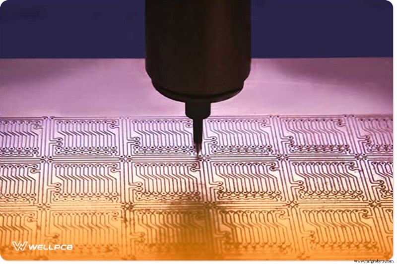
In the past, drilling PCBs involved manual positioning and lever‑pulled drills—an approach that simply couldn’t keep pace with modern boards that may contain over a thousand holes. Today, automated drilling machines equipped with standard PCB drill sizes streamline the process, delivering precise, repeatable results.
Why Standard PCB Drill Sizes Matter
Using industry‑standard drill sizes is essential whether you’re fabricating PCBs yourself or supplying boards to clients. Most manufacturers specify finished hole diameters, allowing their assembly lines to accommodate a range of component footprints. For hobbyists, standard sizes reduce the learning curve and improve consistency.
Choosing the Right Drill Size
When selecting a drill, consider the board’s thickness and the desired hole diameter. The aspect ratio—the ratio of hole depth to diameter—must be compatible with the drill’s capability. For example, a 0.006‑inch hole typically requires a 0.062‑inch drill bit, while a 0.012‑inch hole calls for a bit less than 0.125‑inch. Many PCB materials come with recommended drill sizes, simplifying the selection process.
Vias—small conductive pathways that pass through the board—often need drilling followed by plating. Holes smaller than 0.001‑inch are challenging for standard equipment; specialized micro‑drills or EDM may be required.

Minimizing Waste and Ensuring Fit
When a component’s pin pitch is X mm, drill a hole of X + 0.3 mm. For a 0.4 mm pin pitch, a hole around 0.7–0.8 mm is typical. Oversized holes waste material and complicate soldering; undersized holes hinder component insertion and may lead to voids during plating.
Designing boards with standard drill sizes also helps meet panel limits: Standard Surface‑Mount (SSS) panels generally allow up to 500 holes, while Design‑Special (DSS) panels may accommodate up to 2,000. Prefer metric units (e.g., 0.1 mm, 5.0 mm) for consistency and ease of measurement.

Reference: Standard Drill Size Chart
The table below lists drill diameters in metric, wire gauge, letter, and fractional inches. If you’re unsure of the correct size for your application, consult a PCB standard drill size chart.

Hole‑Making Fundamentals
Precision drilling hinges on two key factors:
- Tolerance – Sharp bits and proper tooling reduce deviation.
- Depth – Decide whether you need a blind hole or a through‑hole based on the board’s stack‑up.
Conclusion
With a clear understanding of standard PCB drill sizes and the right tools, you can achieve accurate, efficient drilling while minimizing waste. Select drills that match your board’s specifications, adhere to industry standards, and you’ll be set for reliable PCB fabrication.
Industrial Technology
- Enhancing Product Durability: Mastering Polyurethane Impact Resistance
- Synergizing Lean Production with Industry 4.0: Bosch’s Proven Success
- Optimize Injection-Molded Parts: Professional Finishing Options for Superior Performance
- Automatic Street Light Control System with LDR and BC‑547 Transistor – Simple, Reliable, Energy‑Saving
- Top 3 Strategies for SMBs to Successfully Expand Internationally
- Essential Safety Protocols for Manufacturing Workers: A Comprehensive Guide
- Effective Strategies for Managers to Keep Factories Cool and Productive
- 6 Essential Questions to Guide Your Work Platform Selection
- Master 4‑Axis Machining in Autodesk Fusion 360: Advanced Techniques & Toolpath Wrap
- How Reverse Logistics Software Transforms Returns Management