


Understanding the Iron-Carbon Phase Diagram: Key Insights for Metallurgy
The Iron-Carbon Phase Diagram
The phase diagrams are very important tools in the study of alloys for solutions of many practical problems in metallurgy. These diagrams define the regions of the stability of a phase which can exist in an alloy system under the condition of constant atmospheric pressure. For a binary system, the coordinates of these diagrams are temperature and composition. The inter-relationships between the phases, the temperature and the composition in an alloy system are normally presented by phase diagram only under equilibrium conditions. Such conditions occur during slow heating and cooling rates of the alloys, when the kinetics of transformations do not play an important role.
In their simplest form, iron and steels are alloys of iron (Fe) and carbon (C). There are three types of ferrous alloys. These alloys consist of (i) iron having a C content of less than 0.0008 % at room temperature, (ii) steels with C content ranging from 0.008 % to 2.14 % (normally less than 1 %) and having a microstructure consisting ferrite and cementite), and (iii) cast iron with C content ranging from 2.14 % to 6.7 % (normally less than 4.5 %). The study of the constitution and structure of iron and steels starts with the iron-carbon (Fe-C) phase diagram (Fig 1). Fe-C phase diagram is also used as the basis for the understanding of the heat treatment processes.
Many of the basic features of Fe-C system influence the behaviour of even the most complex alloy iron and steels. For example, the phases found in the simple binary Fe-C system persist in complex steels, but it is necessary to examine the effects alloying elements have on the formation and properties of these phases. The Fe-C diagram provides a valuable foundation on which the knowledge of both plain carbon and alloy steels can be build.
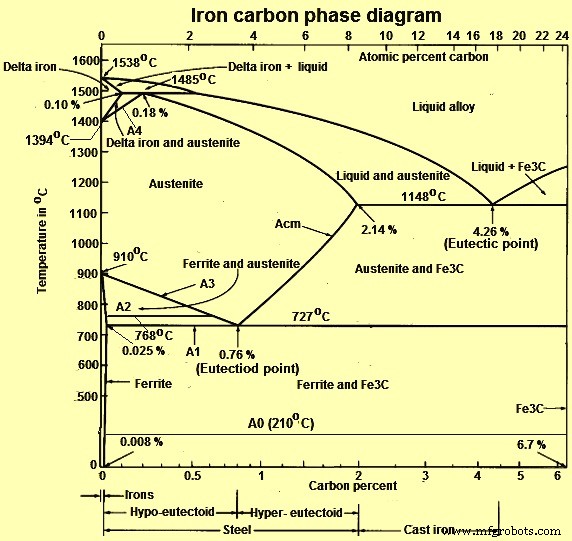
Fig 1 Iron carbon phase diagram
C is an interstitial impurity in Fe. It forms a solid solution with alpha, gamma and delta phases of iron. Maximum solubility of C in alpha iron is 0.025 % at 727 deg C. Body centred cubic (BCC) iron has relatively small interstitial positions. Maximum solubility of C in the face centred cubic (FCC) gamma iron is 2.14 % at 1148 deg C. FCC iron has larger interstitial positions. Mechanical properties of iron-carbon alloys (iron and steels) depend on their microstructure, that is, how the different phases are mixed.
The iron –carbon phase diagram in Fig 2 actually shows two diagrams namely (i) the stable iron-graphite diagram (red lines), (ii) and the metastable Fe-Fe3C diagram. Cementite is metastable, and the true equilibrium is to be between iron and graphite (C). Although graphite occurs extensively in cast irons, it is usually difficult to obtain this equilibrium phase in steels. The stable condition usually takes a very long time to develop specially in the low temperature and low carbon range. Hence, the normal equilibrium diagram which is generally used is the metastable Fe-Fe3C diagram because it is relevant to the behaviour of most steels in practice.
The details of the stable and metastable phase diagrams of the Fe-C system, especially on the Fe-rich side, are known much better than any other binary systems with similar complexity. However, there are still substantial areas where the phase diagram has not been well established such as in the temperature, composition, and pressure ranges not related directly to iron and steel making.
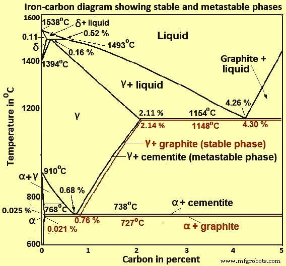
Fig 2 Iron-carbon diagram showing stable and metastable phases
There are some important metallurgical phases and micro constituents in the iron carbon system. In the Fe–Fe3C system, carbon is an interstitial impurity in Fe. It forms a solid solution with alpha (alpha ferrite), gamma (austenite), and delta (delta ferrite) phases of iron. These are important phases in Fe – Fe3C phase diagram. Between the single-phase fields, there are found regions with mixtures of two phases, such as ferrite and cementite, austenite and cementite, and ferrite and austenite. At the highest temperatures, the liquid phase field can be found and below this are the two phase fields liquid and austenite, liquid and cementite, and liquid and ferrite. In heat treatment of steels, the liquid phase is always avoided. At the eutectic point (4.26 % C), liquid alloy on cooling gets directly converted into austenite and cementite without any two phase field. Similarly, at the Eutectoid point (0.76 % C), austenite phase on cooling gets directly converted into ferrite and cementite without any two phase field. Some important boundaries at single-phase fields have been given special names which facilitate the understanding of the diagram.
Main phases of iron and steels in equilibrium are the following phases.
- Ferrite or alpha-iron phase – It is a stable form of iron at room temperature. It is relatively soft low temperature phase and is a stable equilibrium phase. It transforms to to FCC austenite (gamma phase) at 910 deg C. Ferrite is a common constituent in steels and has a BCC structure, which is less densely packed than the FCC structure. It is soft, and fairly ductile. It is magnetic below 768 deg C. It has low strength and good toughness.
- Austenite or gamma iron phase – Austenite is a high temperature phase. It is a solid solution of C in the FCC iron. Hence, it has a FCC structure, which is a close packed structure. It is a non magnetic and ductile phase. It transform to BCC delta ferrite at 1394 deg C. It is not stable below the eutectic temperature (727 deg C) unless cooled rapidly. Austenite has good strength and toughness.
- Delta ferrite phase – It is solid solution of C in BCC iron. It is stable only at temperature higher than 1394 deg C. It melts at 1538 deg C. It has paramagnetic properties.
- Cementite – It is Fe3C or iron carbide. It is an inter-metallic compound of Fe and C. It has a complex orthorhombic structure and is a metastable phase. It is a hard, brittle phase. It has low tensile strength, good compression strength and low toughness. It decomposes (very slowly, within several years) into alpha ferrite and C (graphite) at the temperature range of 650 deg C to 700 deg C.
On comparing austenite with ferrite, the solubility of carbon is more in austenite with a maximum value of 2.14 % at 1148 deg C. This high solubility of carbon in austenite is extremely important in heat treatment, when solution treatment in the austenite followed by rapid quenching to room temperature allows formation of a supersaturated solid solution of carbon in iron. The ferrite phase is restricted with a maximum carbon solubility of 0.025 % at 727 deg C. Since the carbon range available in common steels is from 0.05 % to 1.5 %, ferrite is normally associated with cementite in one or other form. Similarly, the delta-phase is very restricted and is in the temperature range between 1394 deg C and 1538 deg C/ It disappears completely when the carbon content reaches 0.5 %.
Alloy of eutectoid composition (0.76 % C) when cooled slowly, forms pearlite, which is a layered structure of two phases namely alpha‐ferrite and cementite. Pearlite is the ferrite-cementite phase mixture. It has a characteristic appearance and can be treated as a micro structural entity or micro constituent. It is an aggregate of alternating ferrite and cementite lamellae which degenerates (spheroidizes or coarsens) into cementite particles dispersed with a ferrite matrix after extended holding below 727 deg C. It is a eutectoid and has a BCC structure. It is a partially soluble solution of Fe and C. Mechanically, the pearlite has properties intermediate to soft, ductile ferrite and hard, brittle cementite. It has high strength and low toughness.
Hypo-eutectoid alloys contain pro-eutectoid ferrite (formed above the eutectoid temperature) along with the eutectoid pearlite which contain eutectoid ferrite and cementite. Hyper-eutectoid alloys contain pro-eutectoid cementite (formed above the eutectoid temperature along with pearlite which contain eutectoid ferrite and cementite.
In case of non-equilibrium solidification of Fe-C system some additional type of microstructures can also be formed. Some of these microstructures are given below.
- Bainite – It is a phase between pearlite and martensite. It is a hard metastable micro constituent and consists of non lamellar mixture of ferrite and cementite on an extremely fine scale. Upper bainite is formed at higher temperatures and has a feathery appearance. Lower bainite is formed at lower temperatures and has an acicular appearance. The hardness of bainite increases with decreasing temperature of its formation. It has good strength and toughness.
- Martensite – It is a very hard form of steel crystalline structure. It is named after the German metallurgist Adolf Martens. It is formed by rapid cooling and is hard and brittle. It is a body-centered tetragonal (BCT) form of iron in which some carbon is dissolved. It is formed during quenching, when the face centered cubic lattice of austenite is distorted into the body centered tetragonal structure without the loss of its contained carbon atoms into cementite and ferrite. It is super saturated solution of C atoms in ferrite. It is a hard metastable phase. It has lath morphology when C is less than 0.6 %, plate morphology when C is more than 1 %, and mixture of those in between. It is having high strength and hardness and low toughness.
- Sorbite / troostite – Structures of the lower pearlite stage with very fine flakes are referred to as sorbite and troostite. It is the transformation structures of the pearlite stage which correspond to the increasing cooling rates. However, it changes the structure ratio and the formation of pearlite with regard to flake distance. The structure cannot be seen under an optical microscope.
- Widmanstatten ferrite – It is obtained when hypo-eutectoid plain carbon steel is cooled down rapidly form a temperature above the A3 temperature. Due to the fast cooling, there is little time available the ferrite crystals to nucleate not only on the grain boundary but also within the large austenite grains. They quickly grow into some preferred crystal direction inside the grain and thus become longish. The structure is either in the form of needles (laths) or plates which tend to align along the same direction within one grain.
There are many temperatures and critical points in the Iron-C diagram which are important both from the basic and the practical point of view. These are the temperatures when during cooling, or heating, the transformations of phase as well magnetic take place in them. The temperatures at which the transformations occur in the solid state are called critical temperatures, or critical points. Major temperatures and critical points are given below.
- A0 temperature – It is the Curie temperature when the magnetic to non-magnetic change of cementite occurs on heating. The structure can develop defects such as dislocations, faults and vacancies. Cementite is metallic and ferromagnetic with a Curie temperature of around 210 deg C. When alloyed, metallic solutes substitute on to the iron sites; smaller atoms such as boron replace carbon at interstitial sites.
- A1 temperature – It is the temperature (727 deg C) when the eutectoid transformation occurs. At this temperature pearlite changes to austenite on heating and vice versa
- A2 temperature – It is called the Curie temperature of ferrite (768 deg C), where ferromagnetic ferrite on heating changes to paramagnetic. At this temperature no change in microstructure is involved
- A3 temperature – It is the temperature at which ferrite just starts forming from austenite, on cooling hypo-eutectoid steel or last traces of free ferrite changes to austenite, on heating. Thus, it is the temperature corresponding to gamma + alpha / gamma phase boundary for hypo-eutectoid steel and is a function of carbon content of the steel, as it decreases from 910 deg C at 0 % C to 727 deg C at 0.76 % C. It is also called the upper critical temperature of hypo-eutectoid steels. The temperature interval between A1 and A3 temperatures is called the critical range in which the austenite exists in equilibrium with ferrite.
- Acm temperature – It is the temperature, in a hyper-eutectoid steel, at which pro-eutectoid cementite just starts to form (on cooling) from austenite. It represents the temperature of gamma/gamma + Fe3C phase boundary and, is a function of carbon. Acm line illustrates that solid solubility of carbon in austenite decreases very rapidly from a maximum of 2.14 % at 1148 deg C to a maximum of 0.76 % at 727 deg C, due to greater stability of cementite at lower temperatures. The extra carbon precipitates from austenite as pro-eutectoid cementite in hyper eutectoid steels (also called secondary cementite in cast irons). Separation of cementite from austenite (on cooling) is also accompanied with the evolution of heat.
- A4 temperature – It is the temperature at which austenite transforms to delta iron. The lowest value for this temperature is 1394 deg C which is in case of pure iron. This temperature increases as the carbon percent is increased.
- Ms temperature – It is the temperature at which transformation of austenite to martensite starts during cooling.
- Mf temperature – It is the temperature at which martensite formation finishes during cooling. All of the changes, except the formation of martensite, occur at lower temperatures during cooling than during heating and depend on the rate of change of temperature.
Austenite- ferrite transformation – Under equilibrium conditions, pro-eutectoid ferrite is formed in iron-carbon alloys containing up to 0.76 % of carbon. The reaction occurs at 910 deg C in pure iron, but takes place between 910 deg C and 727 deg C in iron-carbon alloys. However, by quenching from the austenitic state to temperatures below the eutectoid temperature, ferrite can be formed down to temperatures as low as 600 deg C. There are pronounced morphological changes as the transformation temperature is lowered, which normally apply in general to hypo-eutectoid and hyper-eutectoid phases, although in each case there are variations due to the precise crystallography of the phases involved. For example, the same principles apply to the formation of cementite from austenite, but it is not difficult to distinguish ferrite from cementite morphologically.
Austenite-cementite transformation – There are different morphologies of cementite which are formed at progressively lower transformation temperatures. The initial development of grain boundary allotriomorphs is very similar to that of ferrite and the growth of side plates or Widmanstatten cementite follows the same pattern. The allotriomorph has a shape which does not reflect its internal crystalline symmetry. This is because it tends to nucleate at the austenite grain surfaces, thus forming layers which follow the grain boundary contours. The cementite plates are more rigorously crystallographic in form, despite the fact that the orientation relationship with austenite is a more complex one. As in the case of ferrite, most of the side plates originate from grain boundary allotriomorphs, but in the cementite reaction more side plates nucleate at twin boundaries in austenite.
Austenite-pearlite reaction – Pearlite is the most familiar microstructure in the iron carbon phase diagram. It was discovered by Sorby over a century ago, who correctly assumed it to be a lamellar mixture of iron and iron carbide. It is a very common constituent of a wide variety of steels, where it provides a substantial contribution to strength. Lamellar eutectoid structures of this type are widespread in the metallurgy of steels. These structures have much in common with the cellular precipitation reactions. Both types of reaction occur by nucleation and growth, and are, hence, diffusion controlled. Pearlite nuclei occur on austenite grain boundaries, but it is clear that they can also be associated with both pro-eutectoid ferrite and cementite. In commercial steels, pearlite nodules can nucleate on inclusions.
Manufacturing process
- Iron vs. Steel: Key Differences Explained
- Iron: Properties, History, and Everyday Applications
- Sintering Iron Ore Fines: Enhancing Blast Furnace Efficiency
- Optimizing Low‑Grade Iron Ore: Jigging Techniques for Effective Beneficiation
- Iron‑Carbon Phase Diagram Explained: Key Insights for Steel and Cast Iron
- Selecting the Optimal Grade of Ductile Cast Iron for Your Engineering Needs
- Leading Iron Casting Companies: Excellence in Metal Fabrication
- Why Grey Iron Is the Leading Choice for Forging Applications
- Discover the Key Benefits of Gray Cast Iron in Modern Engineering
- Why Choose Iron Ductile Pipes: Strength, Durability, and Efficiency