


Fundamentals of Pneumatics: Key Concepts & System Applications
Basics of Pneumatics and Pneumatic Systems
Pneumatics has long since played an important role as a technology in the performance of mechanical work. It is also being used in the development of automation solutions. Pneumatic systems are similar to hydraulic systems but in these systems compressed air is used in place of hydraulic fluid.
A pneumatic system is a system that uses compressed air to transmit and control energy. Pneumatic systems are used extensively in various industries. Most pneumatic systems rely on a constant supply of compressed air to make them work. This is provided by an air compressor. The compressor sucks in air from the atmosphere and stores it in a high pressure tank called a receiver. This compressed air is then supplied to the system through a series of pipes and valves.
The word ‘Pneuma’ means air. Pneumatics is all about using compressed air to do the work. Compressed air is the air from the atmosphere which is reduced in volume by compression thus increasing its pressure. It is used as a working medium normally at a pressure of 6 kg/sq mm to 8 kg/sq mm. For using pneumatic systems, maximum force up to 50 kN can be developed. Actuation of the controls can be manual, pneumatic or electrical actuation. Compressed air is mainly used to do work by acting on a piston or vane. This energy is used in many areas of the steel industry.
Advantages of pneumatic systems
Pneumatic systems are widely used in different industries for the driving of automatic machines. Pneumatic systems have a lot of advantages.
- High effectiveness – There is an unlimited supply of air in the atmosphere to produce compressed air. Also there is the possibility of easy storage in large volumes. The use of compressed air is not restricted by distance, as it can easily be transported through pipes. After use, compressed air can be released directly into the atmosphere without the need of processing.
- High durability and reliability – Pneumatic system components are extremely durable and cannot be damaged easily. Compared to electromotive components, pneumatic components are more durable and reliable.
- Simple design – The designs of pneumatic system components are relatively simple. They are thus more suitable for use in simple automatic control systems. There is choice of movement such as linear movement or angular rotational movement with simple and continuously variable operational speeds.
- High adaptability to harsh environment – Compared to the elements of other systems, compressed air is less affected by high temperature, dust, and corrosive environment, etc. Hence they are more suitable for harsh environment.
- Safety aspects – Pneumatic systems are safer than electromotive systems because they can work in inflammable environment without causing fire or explosion. Apart from that, overloading in pneumatic system only leads to sliding or cessation of operation. Unlike components of electromotive system, pneumatic system components do not burn or get overheated when overloaded.
- Easy selection of speed and pressure – The speeds of rectilinear and oscillating movement of pneumatic systems are easy to adjust and subject to few limitations. The pressure and the volume of the compressed air can easily be adjusted by a pressure regulator.
- Environmental friendly – The operation of pneumatic systems do not produce pollutants. Pneumatic systems are environmentally clean and with proper exhaust air treatment can be installed to clean room standards. Therefore, pneumatic systems can work in environments that demand high level of cleanliness. One example is the production lines of integrated circuits.
- Economical – As the pneumatic system components are not expensive, the costs of pneumatic systems are quite low. Moreover, as pneumatic systems are very durable, the cost of maintenance is significantly lower than that of other systems.
Limitations of pneumatic systems
Although pneumatic systems possess a lot of advantages, they are also subject to several limitations. These limitations are given below.
- Relatively low accuracy – As pneumatic systems are powered by the force provided by compressed air, their operation is subject to the volume of the compressed air. As the volume of air may change when compressed or heated, the supply of air to the system may not be accurate, causing a decrease in the overall accuracy of the system.
- Low loading – As the cylinders used in pneumatic systems are not very large, a pneumatic system cannot drive loads that are too heavy.
- Processing required before use – Compressed air must be processed before use to ensure the absence of water vapour or dust. Otherwise, the moving parts of the pneumatic components may wear out quickly due to friction.
- Uneven moving speed – As air can easily be compressed, the moving speeds of the pistons are relatively uneven.
- Noise – Noise is usually produced when the compressed air is released from the pneumatic components.
Components of pneumatic systems
Pneumatic cylinders, rotary actuators and air motors provide the force and movement for the most of pneumatic systems, for holding, moving, forming, and processing of materials. To operate and control these actuators, other pneumatic components are needed such as air service units for the preparation of the compressed air and valves for the control of the pressure, flow and direction of movement of the actuators. A basic pneumatic system consists of the following two main sections.
- Compressed air production, transportation, and distribution system
- Compressed air consuming system
The main components of the compressed air production, transportation, and distribution system consist of air compressor, electric motor and motor control centre, pressure switch, check valve, storage tank, pressure gauge, auto drain, air dryer, filters, air lubricator, pipelines, and different types of valves. The main components of air consuming system consist of intake filter, compressor, air take off valve, auto drain, air service unit, directional valve, actuators, and speed controllers. Basic components of the pneumatic system are shown in Fig 1.
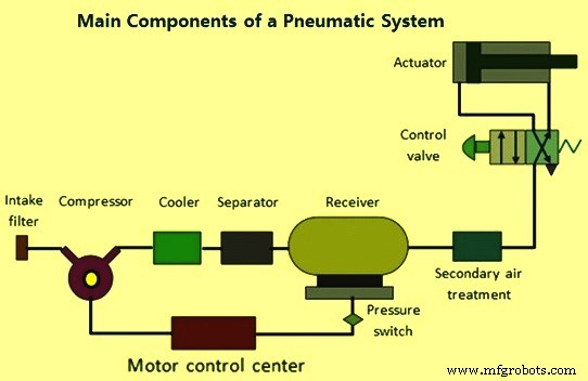
Fig 1 Major components of pneumatic system
Intake filter also known as air filter is used to filter out the contaminants from the air.
Air compressor converts the mechanical energy of an electric or combustion motor into the potential energy of compressed air. There are several types of compressors which are used in the compressed air systems. Compressors used for generation of compressed air is selected on the basis of desired maximum delivery pressure and the required flow rate of the air The types of compressors in the compressed air systems are (i) piston or reciprocating compressors, (ii) rotary compressors, (iii) centrifugal compressors, and (iv) axial flow compressors. Reciprocating compressors are (i) single stage or double stage piston compressor, and (ii) diaphragm compressor. Rotary compressors are (i) sliding vane compressor, and (ii) screw compressor.
Electric motor transforms electrical energy into mechanical energy. It is used to drive the air compressor.
The compressed air coming from the compressor is stored in the air receiver. The purpose of air receiver is to smooth the pulsating flow from the compressor. It also helps the air to cool and condense the moisture present. The air receiver is to be large enough to hold all the air delivered by the compressor. The pressure in the receiver is held higher than the system operating pressure to compensate pressure loss in the pipes. Also the large surface area of the receiver helps in dissipating the heat from the compressed air.
For satisfactory operation of the pneumatic system the compressed air needs to be cleaned and dried. Atmospheric air is contaminated with dust, smoke and is humid. These particles can cause wear of the system components and presence of moisture may cause corrosion. Hence it is essential to treat the air to get rid of these impurities. Further during compression operation, air temperature increases. Therefore cooler is used to reduce the temperature of the compressed air. The water vapour or moisture in the air is separated from the air by using a separator or air dryer.
The air treatment can be divided into three stages. In the first stage, the large sized particles are prevented from entering the air compressor by an intake filter. The air leaving the compressor may be humid and may be at high temperature. The compressed air from the compressor is treated in the second stage. In this stage temperature of the compressed air is lowered using a cooler and the air is dried using a dryer.
Air drying system can be adsorption type, absorption type, refrigeration type, or the type that uses semi permeable membranes. Also an inline filter is provided to remove any contaminant particles present. This treatment is called primary air treatment. In the third stage which is the secondary air treatment process, further filtering is carried out.
Lubrication of moving parts of cylinder and valves is very essential in pneumatic system. For this purpose compressed air lubricators are used ahead of pneumatic equipment. Lubricator introduces a fine mist of oil into the compressed air. This helps in lubrication of the moving components of the system to which the compressed air is applied. Correct grade of lubricating oil usually are with kinematic viscosity around 20- 50 centistokes.
Control valves are used to regulate, control and monitor for control of direction flow, pressure etc. The main function of the control valve is to maintain constant downstream pressure in the air line, irrespective of variation of upstream pressure. Due to the high velocity of the compressed air flow, there is flow-dependent pressure drop between the receiver and load (application). Hence the pressure in the receiver is always kept higher than the system pressure. At the application site, the pressure is regulated to keep it constant. There are three ways to control the local pressures which are given below.
- In the first method, load vents the air into atmosphere continuously. The pressure regulator restricts the air flow to the load, thus controlling the air pressure. In this type of pressure regulation, some minimum flow is required to operate the regulator. If the load is a dead end type which draws no air, the pressure in the receiver rises to the manifold pressure. These type of regulators are called as ‘non-relieving regulators’, since the air must pass through the load.
- In the second type, load is a dead end load. However the regulator vents the air into atmosphere to reduce the pressure. This type of regulator is called as ‘relieving regulator’.
- The third type of regulator has a very large load. Hence its requirement of air volume is very high and cannot be fulfilled by using a simple regulator. In such cases, a control loop comprising of pressure transducer, controller and vent valve is used. Due to large load the system pressure may rise above its critical value. It is detected by a transducer. Then the signal is processed by the controller which directs the valve to be opened to vent out the air. This technique is also used when it is difficult to mount the pressure regulating valve close to the point where pressure regulation is needed.
Air cylinders and motors are the actuators which are used to obtain the required movements of mechanical elements of pneumatic system. Actuators are output devices which convert energy from compressed air into the required type of action or motion. In general, pneumatic systems are used for gripping and/or moving operations in various industries. These operations are carried out by using actuators. Actuators can be classified into three types which are (i) linear actuators which convert pneumatic energy into linear motion, (ii) rotary actuators which convert pneumatic energy into rotary motion, and (iii) actuators to operate flow control valves- these are used to control the flow and pressure of fluids such as gases, steam or liquids. The construction of hydraulic and pneumatic linear actuators is similar. However they differ at their operating pressure ranges. Typical pressure of hydraulic cylinders is about 100 kg/sq mm and that of pneumatic cylinders is around 10 kg/sq mm.
Distribution of compressed air
Proper distribution of compressed air is very important for achieving good performance. Some important requirements which are to be ensured are as follows.
- Piping lay out (open or closed loop) with suitable number of drain valves at diagonally opposite corners
- Piping design has important parameters like diameter of pipe for given flow, pressure drop, number and type of fitting and absolute pressure
- Slope of the main horizontal header from compressor which is normally 1:20
- Take off branches from the top of horizontal headers are with U or at 45 deg
- Provision of accumulator with drain cock at the bottom of all vertical headers
- Air service unit connected at right angles to vertical headers
All main pneumatic components can be represented by simple pneumatic symbols. Each symbol shows only the function of the component it represents, but not its structure. Pneumatic symbols can be combined to form pneumatic diagrams. A pneumatic diagram describes the relations between each pneumatic component, that is, the design of the system. A typical diagram of a pneumatic system is shown in Fig 2.
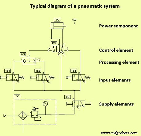
Fig 2 Typical diagram of a pneumatic system
When analyzing or designing a pneumatic circuit, the following four important considerations must be taken into account
- Safety of operation
- Performance of desired functions
- Efficiency of operation
- Costs
Application of pneumatic systems
There are several applications for pneumatic systems. Some of them are pneumatic presses, pneumatic drills, operation of system valves for air, water or chemicals, unloading of hoppers and bins, machine tools, pneumatic rammers, lifting and moving of objects, spray painting, holding in jigs and fixtures, holding for brazing or welding, forming operations, riveting, operation of process equipment etc.
Manufacturing process
- Embedded Systems Fundamentals & Real-World Applications
- Expert Guide to Anaerobic Adhesives and Threadlockers: Applications, Performance, and Best Practices
- Embedded Systems & System Integration: Modern Architecture & Connectivity
- Hydraulics 101: Understanding Fluid Power Systems
- Advanced Flue Gas Cleaning Solutions: Technologies & Systems for Cleaner Air
- SCADA Systems & Industry 4.0: Revolutionizing Remote Process Control
- Professional Crane Conductor Bars & Systems for Reliable Power Delivery
- Hydraulic & Pneumatic Solutions for the Food & Beverage Industry
- Key Components of CNC Machine Systems: A Comprehensive Guide
- Understanding Brushed vs. Brushless DC Motors: Fundamentals & Applications