


Expert Design Strategies to Safeguard High‑Speed USB, HDMI, DisplayPort, and eSATA Interfaces
Second Part of Our Port‑Protection Series: Safeguarding High‑Speed USB, HDMI, DisplayPort, and eSATA Interfaces
High‑speed communication interfaces—USB, HDMI, DisplayPort, eSATA—are the backbone of modern electronics. While they deliver data at impressive rates, the ports that expose these signals are vulnerable to external hazards such as current overloads, voltage transients from lightning, fast‑transient disturbances, and electrostatic discharge (ESD). A robust protection strategy ensures that the integrity of the transmitted data is never compromised, while keeping the product’s size and performance within specifications.
In this article, we build on the first part of the series, which covered power‑over‑Ethernet protection. We now focus on four key protocols:
- USB (Universal Serial Bus) – from 1.0 to the latest USB4
- HDMI (High‑Definition Multimedia Interface) – up to 48 Gbps (v2.1)
- DisplayPort – targeting 77 Gbps (v2.0)
- eSATA (External SATA) – high‑speed external storage
The current maximum bandwidths for each standard are summarized in Table 1.
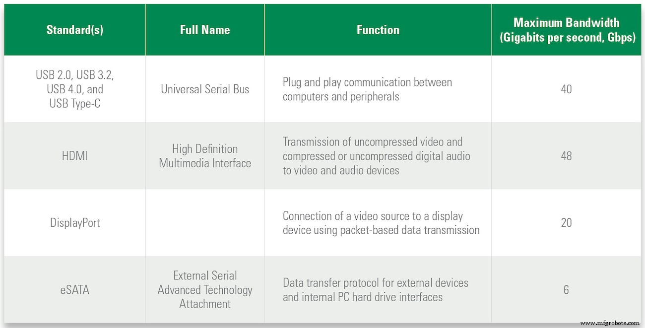
Table 1. Communication protocols, function, and maximum data rate
USB Interfaces
USB is ubiquitous across PCs, peripherals, and test equipment. Since its 1996 debut, the USB‑Implementers Forum has driven successive upgrades—from USB 1.0 to the latest USB4—boosting both data throughput and power delivery. Table 2 details the throughput of each major revision.
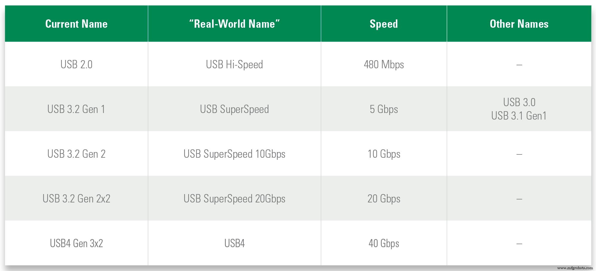
Table 2. Active USB versions and their maximum data transfer rates
USB’s flexible interface supports devices ranging from low‑speed keyboards to high‑bandwidth video capture. It also provides power delivery (PD) revisions that scale from 2.5 W (5 V × 0.5 A) to 100 W (20 V × 5 A). The connectors have evolved in parallel: USB 1.1 uses the 4‑pin mini‑USB, USB 2.0 adopts the 4‑pin Type‑A, and USB 3.x/4.0 use the high‑density 24‑pin Type‑C. Figure 1 illustrates the pin configurations and relative sizes.

Figure 1. USB connectors designed for the various USB standards
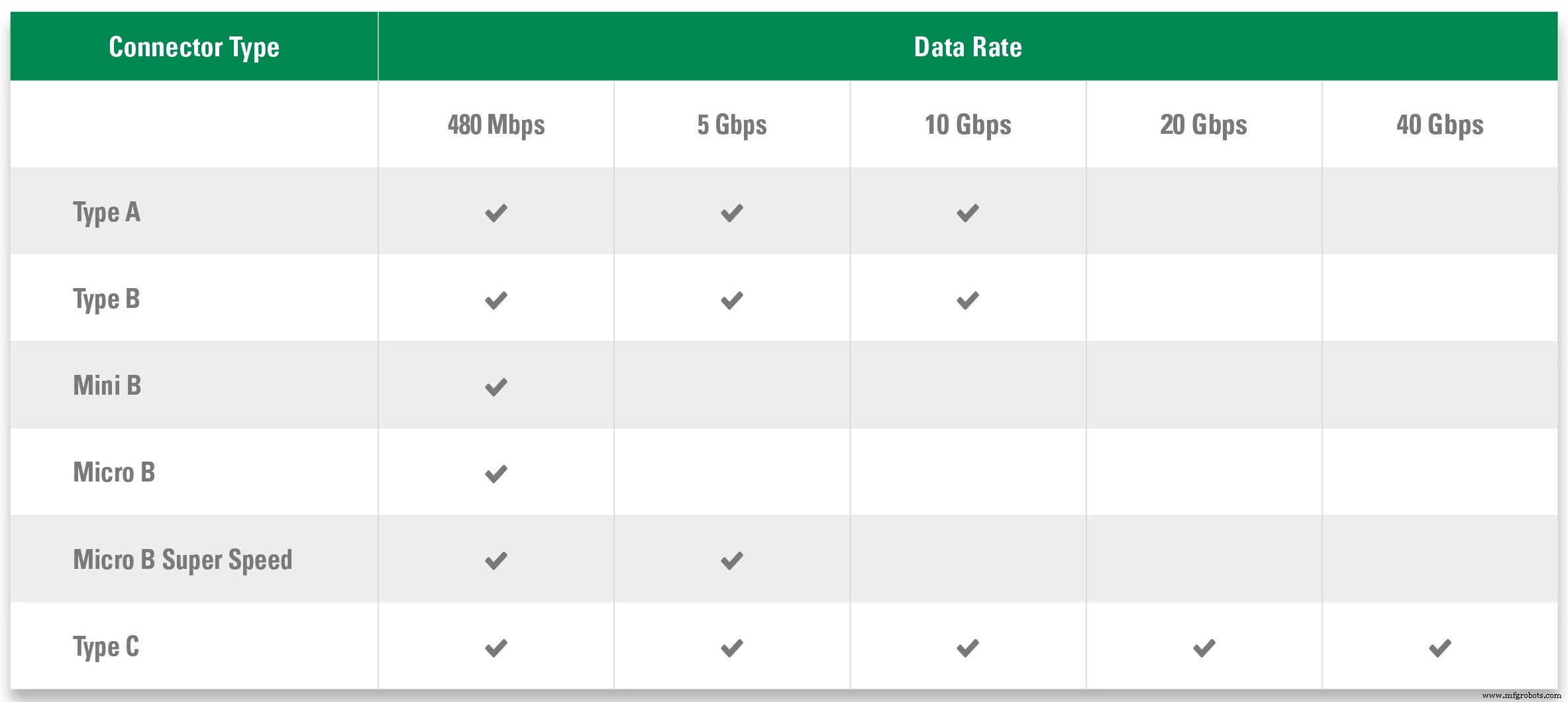
Table 3. Maximum data rates for USB connector types
Protecting a USB 2.0 Interface
A USB 2.0 port comprises a VBUS power line and two differential data lines, as shown in Figure 2a.
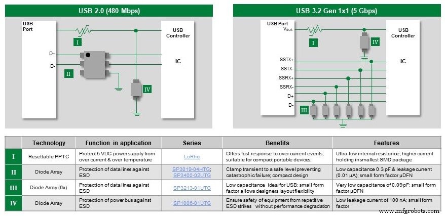
Figure 2. Recommended protection components for USB 2.0 and USB 3.2 interfaces
The VBUS line, often sourced from mains power, is exposed to overloads and voltage spikes. A resettable polymer positive temperature coefficient (PPTC) fuse on VBUS limits fault current while automatically resetting once the fault condition clears. Typical PPTC fuses offer:
- Ultra‑low resistance (mΩ to 2 Ω) under normal operation
- Current ratings from 100 mA to 9 A
- Fast‑trip time and compact surface‑mount footprints (0402–2920)
- UL/TÜV approval for safety compliance
To guard against AC‑line transients and ESD, mount a uni‑directional TVS diode array on VBUS. Such arrays can absorb up to 40 A from fast transients and 5 A from lightning, withstand ±30 kV ESD, and present a leakage current of only 0.5 µA in 5 V circuits—all in a 0201 package.
The two data lines also demand protection. A 4‑channel TVS array is ideal, offering:
- ESD handling of ±22 kV (through‑air) and –10 kV (direct contact)
- Capacitance of 0.3 pF per pin, preserving eye diagram integrity
- Leakage currents as low as 10 nA
With these three components—PPTC fuse, VBUS TVS array, and 4‑channel data line TVS—the USB 2.0 port is fully shielded.
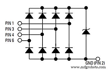
Figure 3. 4‑channel TVS diode array with a Zener diode for transient voltage protection
Protecting a USB 3.2 Interface
USB 3.2 adds six high‑speed data and control lines to the existing VBUS line. The same PPTC fuse and VBUS TVS solution applies. For the six data lines, discrete TVS diodes—each with low capacitance (0.09 pF pin‑pin) and low leakage (≤20 nA)—provide robust protection without compromising the 10 Gbps data rate.
Protecting USB 3.2/USB 4.0 Type‑C with Power Delivery
High‑power Type‑C connectors (up to 100 W) can suffer resistive shorts from dust or debris. Deploy a digital temperature indicator on the Configuration Channel (CC) to monitor thermal stress and trigger a safe shutdown. Refer to the USB‑Type‑C specification for implementation details.
For transient protection, select TVS arrays tailored to SuperSpeed lines—prioritizing minimal capacitance—and use AEC‑Q101 qualified components for automotive applications.
Protecting HDMI, DisplayPort, and eSATA Interfaces
HDMI (v2.1) delivers up to 48 Gbps, DisplayPort (v2.0) targets 77 Gbps, and eSATA offers high‑speed external storage. A single 4‑line TVS array can safeguard all three, as illustrated in Figure 5.

Figure 5. Recommended protection for HDMI, DisplayPort, and eSATA interfaces
Figure 6 shows the 4‑line TVS array configuration.
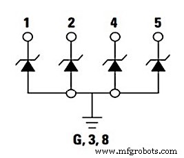
Figure 6. TVS diode array for suppressing voltage transients on four high‑speed data lines
The array offers:
- Ultra‑low capacitance (0.2 pF) to preserve signal integrity
- 25 nA leakage for minimal power loss
- ESD protection up to ±20 kV (air or contact)
- SOD‑883 package to save board space
Enhancing Product Robustness and Reliability
Selecting the right protection components—without degrading signal quality—translates into a more reliable product, reduced warranty claims, and a stronger brand reputation. Engage with component manufacturers early to leverage their expertise and cost‑effective solutions.
Additional References
Download these Littelfuse, Inc. guides for deeper insight:
- Circuit Protection Products Selection Guide
- Littelfuse ® setP Design and Installation Guide
- ESD Protection Design Guide
Industry Articles are a form of content that allows industry partners to share useful news, messages, and technology with All About Circuits readers in a way editorial content is not well suited to. All Industry Articles are subject to strict editorial guidelines with the intention of offering readers useful news, technical expertise, or stories. The viewpoints and opinions expressed in Industry Articles are those of the partner and not necessarily those of All About Circuits or its writers.
Industrial equipment
- 5 Expert Tips for Precision Sheet Metal Design
- Top 5 Design Strategies for Successful Reaction Injection Molding (RIM)
- Proven Design Strategies for Cast Molding with Thermoset Polyurethanes
- Mastering SLA 3D Printing: Expert Design Tips & Best Practices
- Master the Engineering Design Process: Proven Tips for Production Success
- Master High-Speed Digital PCB Design: 9 Essential Impedance Control Tips
- Proven High‑Speed PCB Layout Tips for Reliable Designs
- Expert Design Guidelines for High-Quality Injection Moulding
- Master High-Speed Aluminum Milling: 6 Expert Tips for Precision & Speed
- 10 Expert Tips for Seamless Hydraulic Hose Design & Maintenance