


Choosing the Right Redriver or Retimer to Extend PCIe Signal Range
Redriver and retimer solutions are essential for extending the reach of PCIe® signals in modern compute and NVMe™ storage systems. This guide explains how to select the optimal device for today’s high‑performance workloads and tomorrow’s emerging standards.
The relentless push toward higher data rates in cloud computing and data‑center infrastructures places severe demands on signal integrity. As throughput climbs, the maximum viable transmission distance shrinks, limiting system scalability. Both redrivers and retimers can mitigate these losses, yet each presents distinct trade‑offs that must be understood before deployment.
This article provides a practical framework for choosing between a redriver or a retimer, detailing how each technology extends PCIe® reach and what factors influence their suitability for compute and NVMe™ storage environments.
The PCIe Signal Integrity Challenge
PCIe® remains the dominant high‑speed interface for servers and data‑center networking. Its data rates have evolved from Gen1 (2.5 GT/s) to Gen5 (32 GT/s), with Gen6 projected to double that once again. The higher frequencies required for these rates exacerbate attenuation and dispersion on standard FR4 PCBs, which remain the most economical substrate but suffer significant loss above 10 GHz.
Higher‑performance dielectrics such as Megtron 6 offer superior attenuation characteristics—yet they can cost roughly seven times more than FR4. For many designs, the cost premium outweighs the signal‑quality benefits. Figure 1 illustrates how attenuation scales with frequency for both FR4 and Megtron 6.

Where:
W = trace width in mil (5 mil used in this example)
F = frequency in GHz
Df = dissipation factor (loss tangent) of the PCB material
Dk = dielectric constant of the PCB material
Figure 1. Attenuation vs. Frequency for FR4 and Megtron 6
Connectors further contribute to loss—typical PCIe CEM connectors add ~1.5 dB at 32 Gbps. The PCIe Gen5 standard permits a total channel loss budget of 36 dB, leaving limited margin for PCB and cable loss before signal degradation becomes unacceptable.
Redriver Explained
A redriver is a high‑bandwidth analog amplifier that uses a Continuous‑Timeline Equalizer (CTLE) on the receive side to counter frequency‑dependent attenuation. Optional pre‑emphasis on the transmit side can shape the waveform to improve eye closure. Because redrivers are protocol‑agnostic, they lack link‑training logic and therefore cannot adapt to PCIe’s embedded link‑training sequence.
The key benefits of a redriver are its low cost, modest power consumption, and straightforward integration. However, it also amplifies all signal noise, adding its own jitter floor—typically 8 ps of intrinsic jitter—and cannot correct non‑ISI jitter. Redrivers are generally limited to Gen1–Gen3 PCIe links and become impractical beyond 16 Gbps due to excessive noise accumulation.
Figure 2 shows a typical single‑lane redriver block diagram.
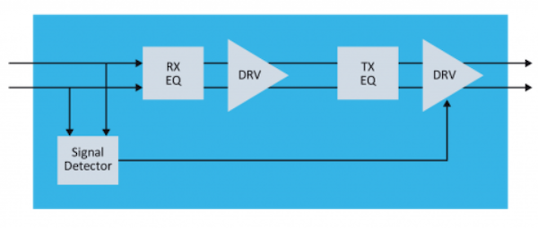
Figure 2. Single‑lane redriver block diagram
Redrivers Have Their Limits
While a redriver can extend trace lengths for low‑complexity Gen1–Gen3 systems, it fails to compensate for the higher attenuation and stricter timing budgets of Gen4 (16 Gbps) and Gen5 (32 Gbps) links. Cascading multiple redrivers is counterproductive because each stage adds its own noise, effectively doubling the jitter budget. Consequently, redrivers are unsuitable for data‑center workloads that require long‑reach PCIe links at 16 Gbps or higher.
Retimer to the Rescue
Starting with PCIe Gen4, the standard explicitly requires a retimer for high‑speed links. A retimer is physically layer‑aware and implements full link‑training and recovery logic. It includes a Clock and Data Recovery (CDR) block that re‑extracts the embedded clock, a serializer/deserializer (SERDES) pair, and an eye‑monitoring subsystem for real‑time diagnostics.
Figure 3 presents a high‑level block diagram of a bi‑directional single‑lane retimer.
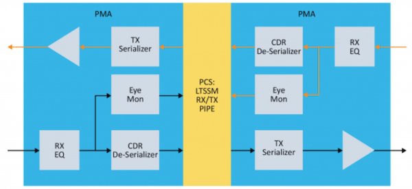
Figure 3. Retimer block diagram
Typical retimers come in x4, x8, or x16 configurations, providing 4, 8, or 16 physical lanes, respectively. Their architecture fully regenerates the data stream, eliminating insertion loss and preserving the signal’s jitter budget. This capability makes retimers indispensable for high‑throughput, long‑reach PCIe applications such as NVMe SSDs, 400 Gbps Ethernet, and accelerator interconnects.
Table 1 contrasts the essential attributes of redrivers and retimers.
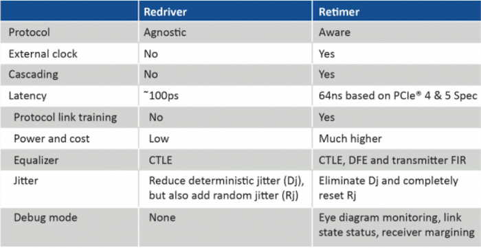
Table 1. Redriver vs. Retimer Comparison
Examples of Retimers in PCIe Applications
Retimers are now a mandatory component in many data‑center topologies. Figure 4 shows a typical server architecture where a retimer sits between the CPU’s root complex and the backplane or add‑in card, enabling signal expansion over cables, riser cards, or additional switches.
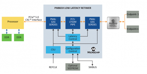
Figure 4. Server example with PCIe retimer
Common configurations include:
• CPU ↔ Retimer ↔ Add‑in Card (AIC)
• CPU ↔ Retimer ↔ Riser Card ↔ AIC
• CPU ↔ Retimer ↔ Cable ↔ Switch ↔ AIC
• CPU ↔ Retimer ↔ Cable ↔ AIC
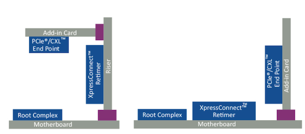
Figure 5. Retimer on riser card and motherboard to AIC
In summary, redrivers can still be valuable for low‑speed, simple designs, but for any application requiring >16 Gbps—whether PCIe, USB 4.0, or Thunderbolt 3.0—retimers provide the necessary signal regeneration and compliance with modern link‑training protocols.
References
- High‑Speed Serial Bus Repeater Primer (PDF)
- PCI‑SIG® Educational Webinar Series 2019 (PDF)
- AN 766: Intel® Stratix® 10 Devices, High‑Speed Signal Interface Layout Design Guideline (PDF)
- PCI Express Base Specification Revision 5.0, Version 1.0, 2019
Industry Articles are a form of content that allows industry partners to share useful news, messages, and technology with All About Circuits readers in a way editorial content is not well suited to. All Industry Articles are subject to strict editorial guidelines with the intention of offering readers useful news, technical expertise, or stories. The viewpoints and opinions expressed in Industry Articles are those of the partner and not necessarily those of All About Circuits or its writers.
Industrial equipment
- Select the Ideal Trash Pump for Reliable Dewatering
- How to Pick the Best CNC Lathe: Automatic vs. Multi‑Spindle Options
- How Selecting the Right Hydraulic Clamps Cuts Cycle Times & Boosts Efficiency
- 10 Expert Tips for Selecting a Trusted PCB Manufacturer & Supplier in China
- Choosing the Right LED Power Supply: A Comprehensive Guide
- Choosing the Right Laser Cutting System for Maximum ROI and Precision
- How to Pick the Ideal CNC Plasma Table for Your Workshop
- Choosing the Right Press: Expert Guide to Mechanical, Hydraulic, and Servo Options
- 3 Essential Factors for Selecting the Ideal Vacuum Pump Technology
- Choosing the Right Air Compressor: Balancing PSI, CFM, and Horsepower for Cost‑Effective Performance