



Cobots 2026: How Collaborative Robots Work and Why They Matter

By the EVST Editorial Team · Last updated: June 10, 2026
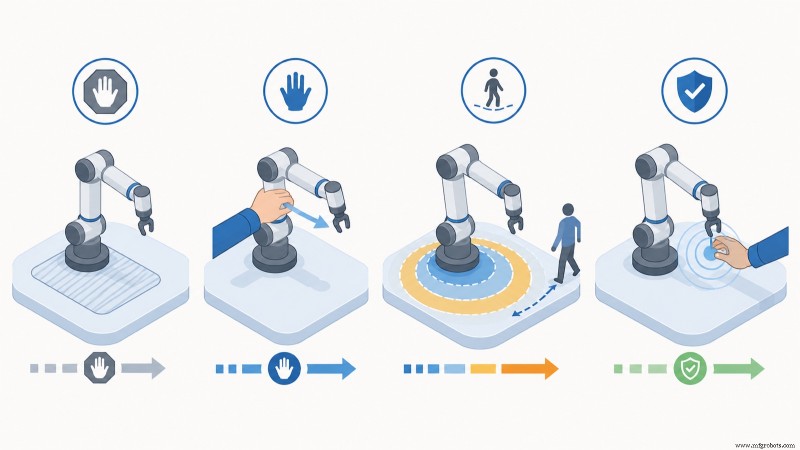
A collaborative robot, or cobot, is a lightweight industrial arm engineered to operate beside people without the need for a safety fence. It achieves this through power‑and‑force limiting: torque sensors in each joint sense contact and immediately stop or retract the arm before a collision can cause injury. ISO/TS 15066 outlines four collaboration modes that define the permissible proximity between a human and a robot. In 2026, cobot payloads typically range from 3 kg to 30 kg, with reaches spanning roughly 600 mm to 1,800 mm.
What Makes a Cobot Different from a Conventional Robot
The term “collaborative” refers to safety capability, not a distinct mechanical class. A cobot remains a 6‑axis articulated arm equipped with servo motors, gearboxes, and encoders on every joint. What sets it apart is the added sensing and control that allows it to share a workspace safely, combined with a design that minimizes injury risk: rounded edges, low moving mass, no pinch points, and speed limits.
Traditional industrial robots are built for speed, payload, and repeatability within a guarded cell, assuming no human presence in the working envelope. Cobots trade peak speed and payload for the ability to operate in a shared space, which in turn changes deployment economics: a cobot cell can forego fencing, light curtains, and the overhead space that a fenced cell requires. This cost‑saving is a key advantage for small and mid‑size manufacturers. For a structured walk‑through of cobot types and selection criteria, see our full guide to cobot types, selection, and applications, which complements this article with a deeper dive into the safety mechanics.
According to the International Federation of Robotics 2025 World Robotics report, collaborative robots remain the fastest‑growing segment of the industrial robot market by unit growth rate, even though they still represent a minority of total installations. Growth is concentrated in electronics assembly, machine tending, and packaging—areas where part weights are low and human‑robot proximity is operationally useful.
How a Cobot Works: The Safety Mechanics
The core technology that enables cobots is how they sense and limit contact force. In 2026, three approaches dominate, and most production cobots combine more than one.
Joint Torque Sensing
Each joint contains a torque sensor—or the controller infers torque from motor current. During normal motion, the controller knows the expected torque profile for the programmed path at the programmed speed. If the measured torque exceeds a threshold, the controller interprets it as an unexpected external force, triggers a protective stop, and brings the arm to a safe position. The reaction time from contact to stop is on the order of milliseconds, keeping the contact force below injury thresholds.
Power‑and‑Force Limiting (PFL)
PFL is the most common collaborative method. The robot is engineered and configured so that, even in a worst‑case contact, the transmitted force and pressure stay below the biomechanical limits defined in ISO/TS 15066 Annex A for the relevant body region. This is achieved through low moving mass, speed limits, rounded geometry, and the torque‑sensing stop described above. PFL allows many cobots to run without fences or light curtains because the robot itself acts as the safety system.
Speed and Separation Monitoring
As an alternative or complement, external safety sensors—such as laser scanners, 3D cameras, or safety mats—track the operator’s position. The robot runs at full speed when no one is near, slows as a person approaches, and stops if the protective separation distance is breached. This enables a faster, heavier robot to behave collaboratively without sacrificing productive speed when the workspace is clear.
In practice, the cleanest deployments combine methods: PFL as the baseline safety, with speed‑and‑separation monitoring layered on to recover throughput when no operator is present. Industry observations from assembly‑line deployments show that a cobot configured purely for worst‑case PFL speed can lose 40 % to 60 % of its potential throughput compared to the same arm allowed to run fast when the workspace is clear—hence hybrid configurations are now the default on higher‑volume lines.
The Four Collaboration Modes Under ISO/TS 15066
ISO/TS 15066:2016 supplements ISO 10218 for collaborative operation and defines four distinct collaboration methods. A single application may use one or combine several. Understanding which mode an application needs is the first step in specifying a safe cobot cell.
| Collaboration mode | How it works | Human‑robot interaction | Typical application |
|---|---|---|---|
| Safety‑rated monitored stop | Robot stops when a person enters the shared space; resumes when they leave | No motion while human is present in the collaborative zone | Manual load/unload of a robot cell, occasional shared‑space tasks |
| Hand guiding | Operator physically moves the arm using a hand‑guide device; robot complies with applied force | Direct physical guidance, robot motion driven by operator | Teaching paths, assisted lifting, low‑volume part positioning |
| Speed and separation monitoring | Robot speed scales with operator distance, measured by safety sensors | Coexistence with dynamic speed reduction, full stop at minimum distance | Mixed cells where humans and robot work in alternating proximity |
| Power and force limiting | Contact force and pressure kept below biomechanical limits by design and control | Direct contact permitted; robot stops on unexpected force | Shared‑task assembly, machine tending, packaging next to operators |
ISO/TS 15066 organizes biomechanical limits by body region: the limits for the face and skull are far stricter than for the upper arm or hand, reflecting the severity of potential injury. A correct risk assessment maps the parts of the robot path where contact is possible to the body regions that could be contacted, then verifies that force and pressure stay under the relevant limit. This is why a cobot that is “safe” for one application is not automatically safe for another: changing the tool, the part, or the layout changes the contact scenarios.
Anatomy of a Cobot: Components and Specifications
A cobot’s specification sheet resembles that of a small industrial robot, with a few collaboration‑specific additions. The parameters that matter most during selection are:
- Payload — the maximum mass at the tool flange, including the gripper or tool. 2026 cobot payloads cluster at 3, 5, 6, 10, 12, 16, 18, 20, and up to the 30 kg class.
- Reach — the radius of the working envelope, typically 500 mm to 1,800 mm. Reach and payload trade off against each other within a product family.
- Repeatability — how precisely the arm returns to a taught point, usually ±0.02 mm to ±0.1 mm depending on size. Repeatability measures consistency, which is what most assembly and tending tasks need.
- Degrees of freedom — six is standard for general 3‑D tasks; seven‑axis cobots add reach‑around flexibility in cluttered spaces.
- Tool flange and I/O — the mounting interface and the electrical/pneumatic connections for grippers and sensors, often routed through the wrist.
- Safety‑rated functions — configurable safety zones, speed limits, force limits, and the safety‑rated monitored stop, all certified to ISO 10218‑1 and IEC 61508/62061 functional safety levels.
The collaboration capability lives mainly in the controller and joint sensing, not in a single visible component. That’s why two arms with identical payload and reach can differ significantly in safety and speed: the difference lies in the safety controller, sensor resolution, and collision‑detection tuning.
Where Cobots Are Applied
Cobots thrive in applications where part weights are modest, human proximity is useful, and the flexibility to redeploy the arm matters more than peak cycle time. The most common application families in 2026 include:
Machine Tending
Loading and unloading CNC machines, injection‑molding presses, and press brakes. The cobot picks a blank, loads the machine, waits for the cycle, and unloads the finished part. Because the operator can still access the machine when the cobot is stopped, the cell stays flexible. Machine tending is the largest cobot application by installed base.
Assembly and Screwdriving
Repetitive fastening, insertion, and pick‑place assembly tasks, often alongside a human who handles judgment‑intensive steps. Force‑controlled cobots excel at insertion tasks (press‑fits, snap‑fits) where a programmed force profile prevents part damage.
Packaging and Palletizing
End‑of‑line case packing and light palletizing. Cobot palletizers handle boxes up to the arm’s payload, building stable stacks on a pallet. For heavier cases, payload becomes the limiting factor and a conventional palletizing robot takes over.
Quality Inspection and Lab Automation
Camera‑ or sensor‑equipped cobots perform repeatable inspection passes, and in laboratories they handle samples, pipettes, and instrument tending. The fenceless layout suits environments where people and equipment share tight benches.
Welding and Surface Finishing
Cobot welding has grown rapidly in job shops, where short seams and low volumes do not justify a fenced welding cell. Cobots also handle sanding, polishing, and deburring with force control. For sustained high‑volume welding on heavy parts, a fenced 6‑axis arm remains the right tool, as covered in our welding robot guide for heavy industry.
Hazardous and Extreme Environments
Explosion‑proof cobots extend collaborative operation into atmospheres with flammable gases, such as chemical, paint, and energy facilities. These require certified enclosure ratings rather than standard cobot housings. See our dedicated guide to explosion‑proof cobots for hazardous environments for certification details.
Cobot vs Industrial Robot: When Each Wins
The choice between a cobot and a conventional industrial robot is an application decision, not a question of which technology is more advanced. The matrix below frames the trade‑off.
| Factor | Collaborative robot | Conventional industrial robot |
|---|---|---|
| Payload | 3 to 30 kg typical | 5 to 800+ kg |
| Speed | Limited for safety; faster with separation monitoring | High, optimized for cycle time |
| Safety guarding | Often fenceless after risk assessment | Fenced cell, light curtains, interlocks |
| Floor space | Compact, no guarding footprint | Larger, includes safety perimeter |
| Redeployment | Fast; arm can be moved between tasks | Slower; cell is semi‑permanent |
| Suited to | Low payload, high mix, human‑adjacent tasks | High volume, high payload, sustained cycle |
For a full decision framework, see our companion analysis, cobot vs industrial robot: which should your factory choose in 2026. In short, a cobot wins when payload is low, the layout benefits from sharing space with people, and the line changes often; a conventional robot wins when volume and payload are high and the cell can be dedicated.
Deploying a Cobot Safely: The Risk Assessment
A common misconception is that a cobot is “safe out of the box.” The arm is built to be collaborative, but the application as a whole—the arm plus tool, part, layout, and task—must be assessed and certified. Under ISO 10218‑2 and ISO/TS 15066, the integrator (often the end user) is responsible for a risk assessment of the complete collaborative application.
- Identify hazards. Map every point in the robot path where contact with a person is possible, plus tool hazards (sharp grippers, hot end effectors), and the part being handled.
- Classify the collaboration mode. Decide which of the four ISO/TS 15066 modes the task uses, and for which phases of the cycle.
- Verify biomechanical limits. For power‑and‑force‑limited operation, confirm that the contact force and pressure for each possible contact stay below the Annex A limit for that body region, by calculation or by measurement with a force‑pressure test device.
- Configure safety functions. Set speed, force, and zone limits in the safety controller, and validate them.
- Document and validate. Record the assessment, validate the as‑built cell against it, and re‑assess whenever the tool, part, or layout changes.
In practice, when EVST application engineers commission a collaborative cell on site, the most frequent finding during validation is that a gripper or a sharp‑edged part creates a contact pressure above the Annex A limit even though the arm itself is within force limits. The fix is usually a gripper redesign, an edge guard, or a speed reduction on the affected path segment—not a different robot. This is the step buyers most often underestimate when they assume a cobot removes the need for safety engineering.
EVST’s Collaborative Robot Range
EVST, headquartered in Chengdu with manufacturing in Wenling, has shipped automation to over 100 countries in seven years. Its collaborative robot line covers payloads from 3 kg through the 30 kg class, with published models including a 3 kg / 620 mm arm, a 6 kg / 917 mm arm, a 12 kg / 1,300 mm arm, and an 18 kg / 900 mm arm. EVST also produces an explosion‑proof collaborative robot for hazardous atmospheres and a catering‑service cobot line, alongside its conventional QJAR industrial robots, SCARA, and delta product families.
EVST’s production line holds IATF 16949 automotive‑grade quality certification, and its products carry CE, SGS, and TUV third‑party certifications. The explosion‑proof cobot is rated for use in flammable atmospheres, extending collaborative operation into environments that standard cobot housings cannot enter. The company also holds one granted invention patent (CN ZL 2020 1 1601091.6), four invention patents in substantive examination, and two software copyrights, supported by a field engineering network spanning 100+ countries for on‑site commissioning and risk‑assessment support.
Frequently Asked Questions
What is a collaborative robot in simple terms?
A collaborative robot is a robot arm built to work safely next to people without a safety fence. It uses torque sensors in its joints to detect contact and stop quickly, and it is designed with low mass, limited speed, and rounded surfaces so that any contact stays below the force and pressure limits that could cause injury, as defined in ISO/TS 15066.
Do cobots really not need a safety fence?
Often, but not automatically. Whether a fence is needed depends on the risk assessment of the complete application, the arm plus its tool, the part, and the task. Many low‑payload, low‑speed applications run fenceless after assessment. But a sharp tool, a heavy or sharp‑edged part, or a high‑speed requirement can force added guarding or speed‑and‑separation monitoring. The cobot enables a fenceless layout; the risk assessment confirms whether one is permissible.
What payload and reach do I need for a cobot?
Add the part weight and the gripper weight to size payload, and leave roughly 20 % to 30 % margin. For machine tending of small parts, a 5 kg to 10 kg arm is common; for palletizing or heavier handling, 16 kg to 30 kg. Reach should cover the full working envelope of the task, typically 600 mm to 1,300 mm for benchtop and machine‑tending work, longer for palletizing.
What is the difference between ISO 10218 and ISO/TS 15066?
ISO 10218 (parts 1 and 2) is the core safety standard for industrial robots and their integration. ISO/TS 15066 is a technical specification that supplements it specifically for collaborative operation, adding the four collaboration modes and the biomechanical force and pressure limits in its Annex A. A collaborative application must satisfy both. For a buyer‑focused breakdown, see our guide to cobot safety standards on the EVST product site.
How fast can a cobot move?
In power‑and‑force‑limited mode, cobot speed is capped so worst‑case contact stays within biomechanical limits, often well below a conventional robot. With speed‑and‑separation monitoring, the same arm can run near its mechanical maximum when no operator is in the protective zone, then slow or stop as a person approaches. Hybrid configurations recover most of the lost throughput while preserving collaborative safety.
Where to Go Next
To match a specific cobot to a payload and reach requirement with a path to a quotation, see the EVST product‑site guide to collaborative robot payload selection from 3 kg to 30 kg. For the safety‑standards detail buyers need before specifying a fenceless cell, see cobot safety standards explained for buyers. For the broader build‑or‑buy decision, read cobot vs industrial robot, and to estimate returns, our cobot ROI calculator for SME manufacturing. For procurement questions, EVST sales can be reached via the contact page.
About the author: The EVST Editorial Team writes about industrial robotics and intelligent manufacturing for engineers and operations leaders evaluating automation projects. EVST (EVS TECH CO., LTD), founded in Chengdu in 2018, has delivered 600+ automation projects and ships to 100+ countries, with IATF 16949 automotive‑grade certification and CE / SGS / TUV third‑party certifications across the QJAR, collaborative robot, SCARA, and delta product families.
Industrial robot
- Key Specs for Choosing the Right Industrial Robot
- KUKA Robots: Precision Packaging Solutions for the Food Industry
- Streamlining Heavy Equipment Production: Motoman Robots for Precision Material Removal
- Fanuc Painting Robots Enhance Efficiency with Chain‑On‑Edge Systems
- Advanced Automated Welding Torch Cleaning Station for Peak Efficiency
- Ensuring Safety in Collaborative Robot Operations
- Robots Drive Mass Personalization of Consumer Products
- Why Investing in Robotics Accelerates Business Growth
- Revolutionizing Manufacturing Health & Safety with Autonomous Robots
- How Fanuc's Material Removal Robots Boost Safety and Efficiency