


Mastering UART: The Universal Asynchronous Receiver/Transmitter Explained
The UART, or Universal Asynchronous Receiver‑Transmitter, remains the most widely adopted hardware protocol for point‑to‑point communication. This guide walks you through configuring a UART, understanding its packet format, and implementing secure frame protocols that are essential during product development.
When correctly configured, a UART can support a variety of serial data streams while requiring only two wires. This minimal wiring reduces cost and complexity, making UART ideal for embedded systems, microcontrollers, and PCs.
We’ll cover UART fundamentals—packet transmission, the standard frame format, and customized frames that add security and compliance value. The article also offers practical steps for interpreting datasheets and configuring UART peripherals.
By the end, you’ll have a solid grasp of UART standards and how to leverage them to enhance new product capabilities.
“The single biggest problem in communication is the illusion that it has taken place.”
—George Bernard Shaw
Communication protocols structure the interaction between devices. They define a common language that ensures data is exchanged reliably. In the embedded world, UART is the de‑facto standard for device‑to‑device hardware communication.
Unlike bus‑based protocols, UART requires only a transmit (Tx) and receive (Rx) line, simplifying board design and lowering power consumption.
Despite its popularity, many implementations overlook proper frame design, which can compromise performance and security. A well‑defined frame protocol is the key to error‑free and protected data exchange.
Asynchronous serial communication means no shared clock line; instead, the transmitter and receiver rely on a matched baud rate to stay in sync.
Interface
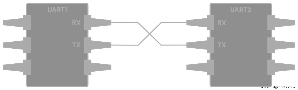
Figure 1. Two UARTs directly communicating.
Each UART exposes two dedicated pins:
- Transmitter (Tx)
- Receiver (Rx)
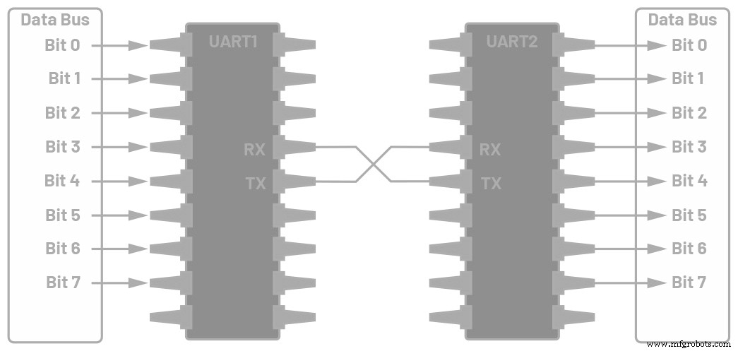
Figure 2. UART interfaced with a data bus.
In this arrangement, the transmitting UART converts parallel data from the bus into a serial bitstream on its Tx line. The receiving UART samples this stream, reassembling the bits into parallel data for the local bus.
Both sides must operate at the same baud rate—the speed in bits per second. A mismatch can lead to framing errors; typical UARTs tolerate up to a 10% baud‑rate deviation.
Table 1 summarizes key UART attributes.
Table 1. UART Summary
| Wires | 2 |
|---|---|
| Supported Baud Rates | 9600, 19200, 38400, 57600, 115200, 230400, 460800, 921600, 1 000 000, 1 500 000 |
| Transmission Method | Asynchronous |
| Maximum Masters | 1 |
| Maximum Slaves | 1 |
Because UART is asynchronous, the transmitter drives a bitstream based on its own clock, while the receiver samples incoming bits using its internal clock. The start bit, data frame, optional parity, and stop bits collectively define the packet.
Data Transmission
Each UART packet contains:
- Start Bit: A transition from high to low that signals the start of a frame.
- Data Frame: 5–8 bits of payload, LSB first. If parity is used, the frame can be 9 bits.
- Parity Bit (optional): Even or odd parity to detect single‑bit errors.
- Stop Bits: One to two high‑level bits marking the frame’s end.
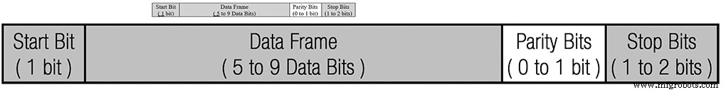
Figure 3. UART packet structure.
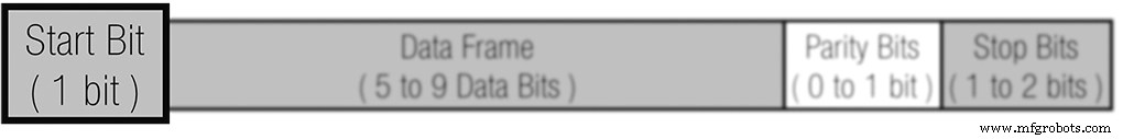
Figure 4. Start bit illustration.
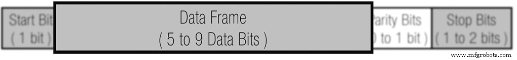
Figure 5. Data frame example.
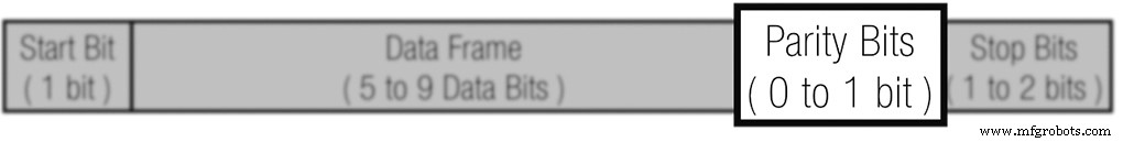
Figure 6. Parity bit usage.
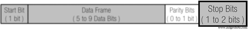
Figure 7. Stop bit illustration.
Transmission Flow
1. Parallel Input: The transmitter receives parallel data from the bus.
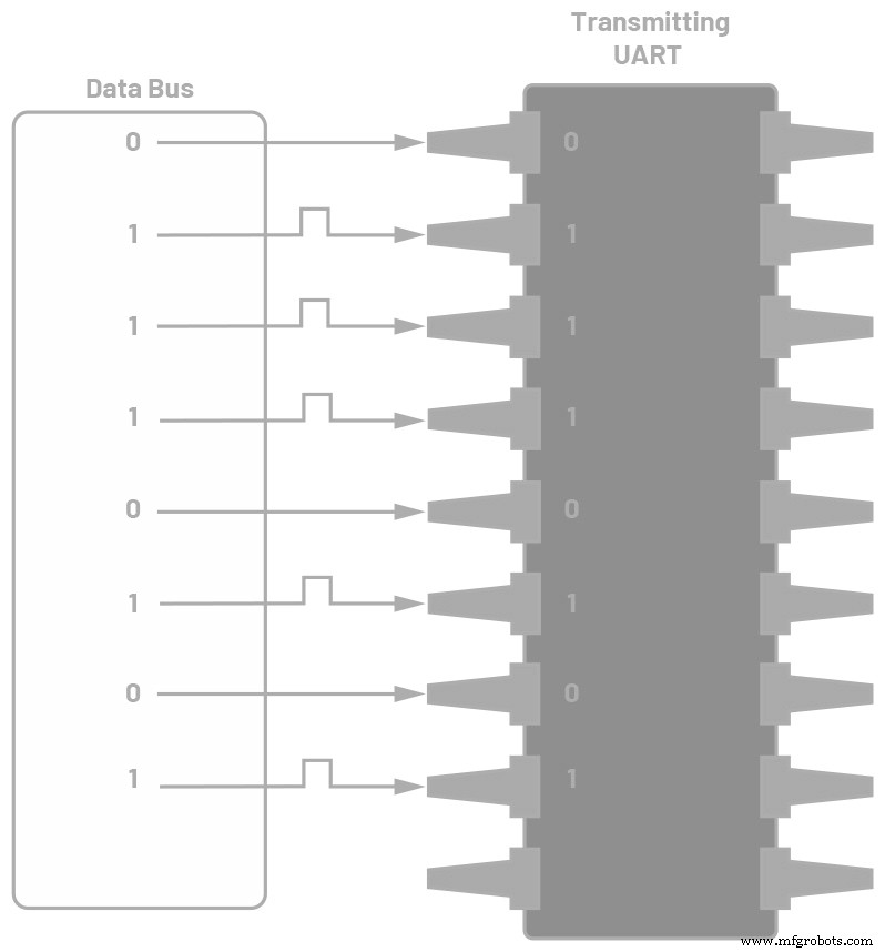
Figure 8. Data bus feeding the transmitter.
2. Frame Assembly: The transmitter prepends the start bit, appends parity and stop bits, forming a complete packet.
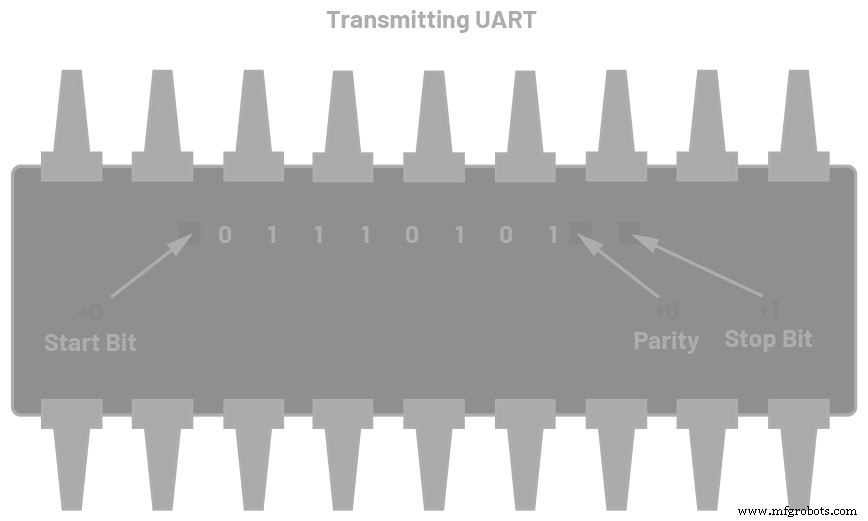
Figure 9. UART packet at the transmitter.
3. Serial Transmission: The packet is sent bit‑by‑bit at the configured baud rate.
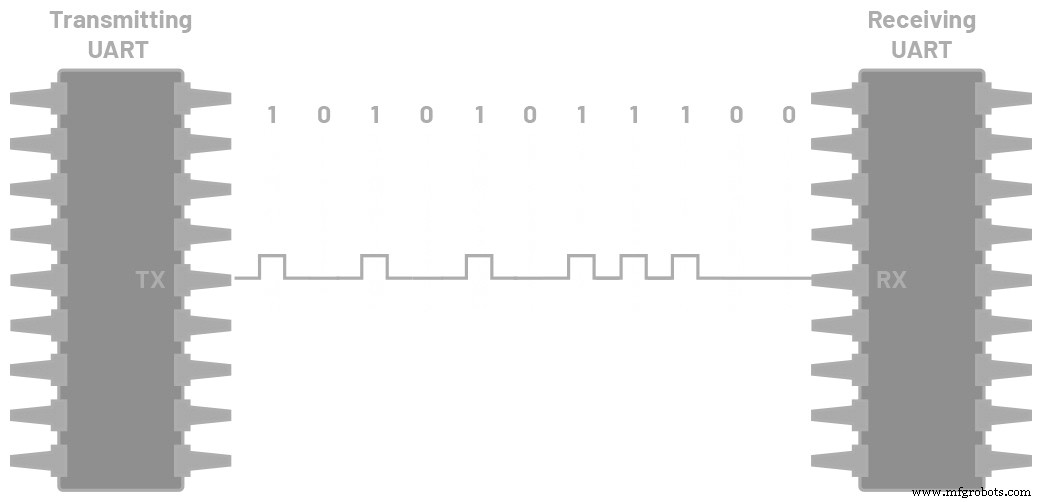
Figure 10. Continuous UART transmission.
4. Reception: The receiver discards framing bits and reconstructs the original data.
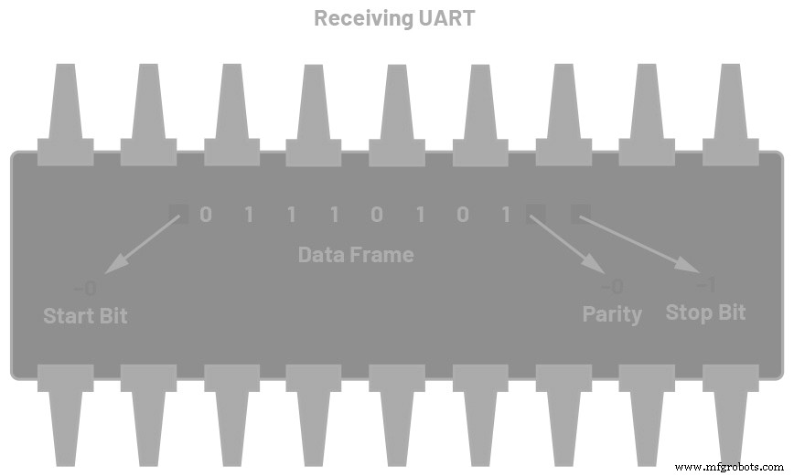
Figure 11. Packet at the receiver.
5. Parallel Output: The receiver converts the serial data back to parallel and forwards it to the local bus.
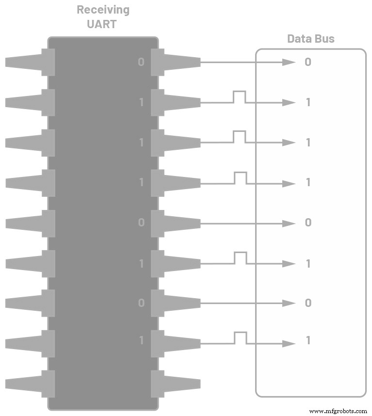
Figure 12. Data flow to the receiving bus.
Custom Frame Protocols
While the standard UART frame is sufficient for many use cases, adding a custom frame layer enhances security and ensures that only intended devices communicate.
By embedding unique headers, trailers, and a CRC, each device can validate that a packet originated from a trusted source. This is particularly valuable in safety‑critical or secure environments.
Figure 13 shows a typical custom frame:
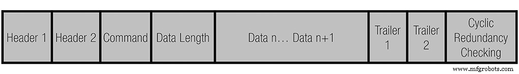
Figure 13. Sample UART frame protocol.
The frame typically contains:
- Header 1 (0xAB) and Header 2 (0xCD) – unique identifiers.
- Command (CMD) – specifies the action.
- Data Length (DL) – number of payload bytes.
- Payload (Data n) – the actual data.
- Trailer 1 (0xE1) and Trailer 2 (0xE2) – closing markers.
- CRC – error‑checking value computed on both ends.
Both sides must use identical framing rules; otherwise, packets will be rejected.
UART Configuration Steps
1. Review the datasheet to understand the UART interface and pin assignments.

Figure 14. Microcontroller datasheet excerpt.
2. Check the memory map for UART registers and addresses.
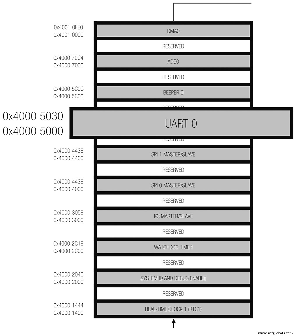
Figure 15. Microcontroller memory map.
3. Define UART port parameters—data bits, parity, stop bits, and operating mode. Sample description:
• 5–8 data bits
• 1, 1½, or 2 stop bits
• None, even, or odd parity
• Full‑duplex, DMA‑enabled, asynchronous transfer
4. Compute the baud rate using the peripheral clock (PCLK) and the MCU’s oversampling and divider registers. The general formula is:
Baud rate = PCLK / ((M + N/2048) × 2OSR + 2 × DIV)
where:
OSR – oversample rate (0–3)
DIV – baud‑rate divider (1–65535)
M – fractional divider MSB (1–3)
N – fractional divider LSB (0–2047)
Example tables below illustrate baud‑rate settings for 26 MHz and 16 MHz PCLKs.
Table 2. Baud Rate Example Based on 26 MHz PCLK
| Baud Rate | OSR | DIV | DIVM | DIVN |
|---|---|---|---|---|
| 9600 | 3 | 24 | 3 | 1078 |
| 115200 | 3 | 4 | 1 | 1563 |
Table 3. Baud Rate Example Based on 16 MHz PCLK
| Baud Rate | OSR | DIV | DIVM | DIVN |
|---|---|---|---|---|
| 9600 | 3 | 17 | 3 | 1078 |
| 115200 | 3 | 2 | 2 | 348 |
5. Configure the UART registers per the datasheet. Key registers include:
Table 4. UART Register Descriptions
| Name | Description |
|---|---|
| UART_DIV | Baud‑rate divider |
| UART_FIBR | Fractional baud‑rate control |
| UART_LCR2 | Line control register (OSR, stop bits, parity) |
Once the registers are programmed, the UART can transmit and receive data reliably.
Why UART Matters
Understanding UART is crucial for engineers who design robust, low‑cost, and high‑throughput serial links. Mastery of framing, baud‑rate calculation, and register configuration ensures data integrity and system reliability.
Common Use Cases
- Debugging – Log messages during firmware development.
- Manufacturing – Real‑time diagnostics and trace logs.
- Over‑the‑air Updates – Deliver firmware changes to embedded devices.
- Verification – Validate device functionality before shipping.
References
“Basics of UART Communication.” Electronics Hub, July 2017.
Campbell, Scott. “Basics of UART Communication.” Circuit Basics. Keim, Robert.
“Back to Basics: The Universal Asynchronous Receiver/Transmitter.” All About Circuits, December 2016.
“What Is UART Protocol? UART Communication Explained.” Arrow.
Embedded
- How Predictive Maintenance Drives Efficiency and Cuts Downtime
- How a Maintenance Storeroom Drives Reliability and Efficiency
- Milling Machines 101: A Comprehensive Guide to Their Function, Components, and Uses
- How AI Is Revolutionizing Robotic Process Automation
- How Automation Drives Value and Efficiency in Modern Manufacturing
- How Shock Absorbers Work: Enhancing Vehicle Balance and Comfort
- What Is a Coupling? Key Functions and Applications in Industrial Machinery
- Exploring Material Flexibility: How Elasticity Determines Performance
- Exploring Diesel Engine Applications in Vehicles and Industrial Generators
- How a Vehicle Heater Core Works: Inside the Automotive Heating System