


Choosing the Right Surface‑Mount Inductor for Your DC‑DC Converter
Understanding the fundamentals of switch‑mode power conversion is essential for selecting the most suitable inductor for any DC‑DC application. This guide, written by Mitchell Rhine, Director of Engineering at Signal Transformer, explains the key concepts and practical steps.
Linear voltage regulators dissipate power as heat: the voltage dropped across the pass transistor multiplied by the load current equals wasted power. In contrast, a switch‑mode DC‑DC converter operates by rapidly turning the power transistor on and off with a duty cycle that, after filtering, delivers the desired output voltage. When the transistor is on, the voltage drop is negligible; when it is off, no current flows. This switching behavior can reduce power dissipation close to zero, enabling efficiencies of up to 95 %—far higher than the roughly 50 % typical of linear regulators. Additionally, the topology of switch‑mode converters allows them to function as buck (step‑down), boost (step‑up), or buck‑boost (inverting) circuits.
For clarity, we focus on the most widely used configuration: a fixed‑frequency buck converter operating in continuous‑mode operation.
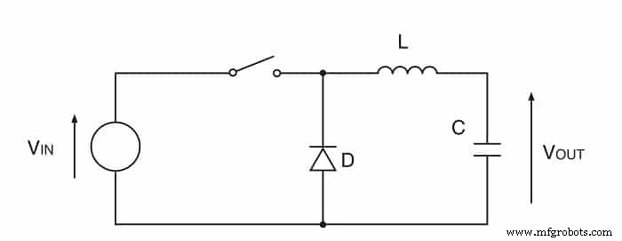
Fig. 1: A simple switching DC‑DC converter.
A basic buck converter comprises a switch, an inductor, a capacitor, and a diode (see Fig. 1). Assuming an ideal switch and diode (Vsw = 0 and Vd = 0) simplifies the analysis, but real designs must account for non‑zero voltage drops.
During the ON period, the diode is reverse‑biased and the current ramps linearly from the input to the output through the inductor. When the switch turns OFF, the inductor’s stored energy forces the current to continue flowing; the diode becomes forward‑biased, allowing the current to decay back to zero before the next ON cycle. This ramping action stores energy in the magnetic core during the ON phase and releases it during the OFF phase.
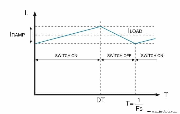
Fig. 2: The inductor current waveform in a buck converter.
The current waveform consists of a DC component equal to the load current (Iload) and an AC component that ramps up and down periodically. Under steady‑state, the current at the end of a switching cycle equals the current at the start.
From the duty‑cycle control, the output voltage is given by
Vout = D · Vin (Equation 1)
where D = ton / (ton + toff) and the switching frequency is fsw = 1 / (ton + toff), with ton = D / fsw.
Adding the voltage drops across the components during the ON period (and assuming Vsw = 0) yields
Vin – Vind – Vout = 0 (Equation 2)
Substituting Vind = L · di/dt, where di ≈ Iramp and dt = ton, we obtain
L · Iramp = (Vin – Vout) · ton (Equation 3)
Equation 3 shows that for a fixed input‑output voltage difference, the product of inductance and current ramp is constant. Increasing L reduces Iramp, while a smaller L enlarges the current ripple. If L is chosen too small, Iramp can become large enough that the inductor current falls to zero for part of the cycle—entering discontinuous‑mode operation.
Large Iramp not only increases output‑voltage ripple but also elevates AC core losses. As a rule of thumb, Iramp should remain a small fraction of the maximum load current to keep ripple and losses acceptable.
The maximum peak current the inductor must withstand in steady‑state operation is
Imax = Iload, max + Iramp/2 (Equation 4)
While Iramp is independent of Iload, it depends on the input voltage. Considering the OFF period, with Vd = 0, we have
Vind – Vout = 0 (Equation 5)
Using Vind = L · di/dt with dt = toff yields
Iramp = Vout · toff / L (Equation 6)
Because Vout is constant, Iramp reaches its maximum when toff (and therefore Vin) is at its highest. This determines the worst‑case Imax via Equation 4.
With the inductance and peak‑current requirements established, the next step is to select an inductor that meets the electrical and mechanical constraints of the board. Shielded or low‑EMI inductors are ideal for dense, high‑performance designs—such as those found in IoT devices—because their magnetic flux is confined, reducing radiated interference.
For example, Signal Transformer’s SCRH series offers magnetically shielded parts with inductances from 1.0 µH to 180 µH, saturation currents from 0.15 A to 5.0 A, and package heights between 1.9 mm and 4 mm. If a larger inductance is needed, the SCxxxxC series provides values from 10 µH to 1 mH, saturation currents from 0.045 A to 8 A, and heights from 2.92 mm to 7.62 mm. Additional series are available for high‑current applications or for those requiring unshielded inductors that maximize efficiency and power handling in a low‑profile package.
Featured image source: Signal Transformer
Internet of Things Technology
- Würth’s MagI³C Power Modules: Precision DC/DC Converters for Adjustable Current and Voltage
- RECOM REC15E‑Z: 15 W DC/DC Converters in a 1 × 1 in Footprint
- Recom REM2 Series: 2W DC/DC Converters Fully Certified for Medical Applications
- Boost Industrial Automation Efficiency with DC/DC Converters
- Choosing a Trusted CNC Machining Shop: A Guide to Reliable CNC Parts Production
- Selecting the Right Proportional Valve for Medical Devices: A Comprehensive Guide
- How to Select a Reliable Scan‑Pac Supplier for High‑Performance Friction Materials
- Choosing the Right Automation Project: A Strategic Guide
- Choosing the Right Coolant for Aluminum Machining: A Professional Guide
- Selecting the Right CNC Manufacturer for Your Prototype Design