


Optimizing Fast‑Response Feedback for Miniaturized Motor Drives
Motor rotation data—position, speed, direction—must be measured with pinpoint accuracy to deliver reliable drivers and controllers for today’s emerging markets. From pick‑and‑place machines that deposit microscopic components on ultra‑compact PCBs to surgical robots and UAVs, the demand for high‑precision motor control continues to climb.
click for larger image
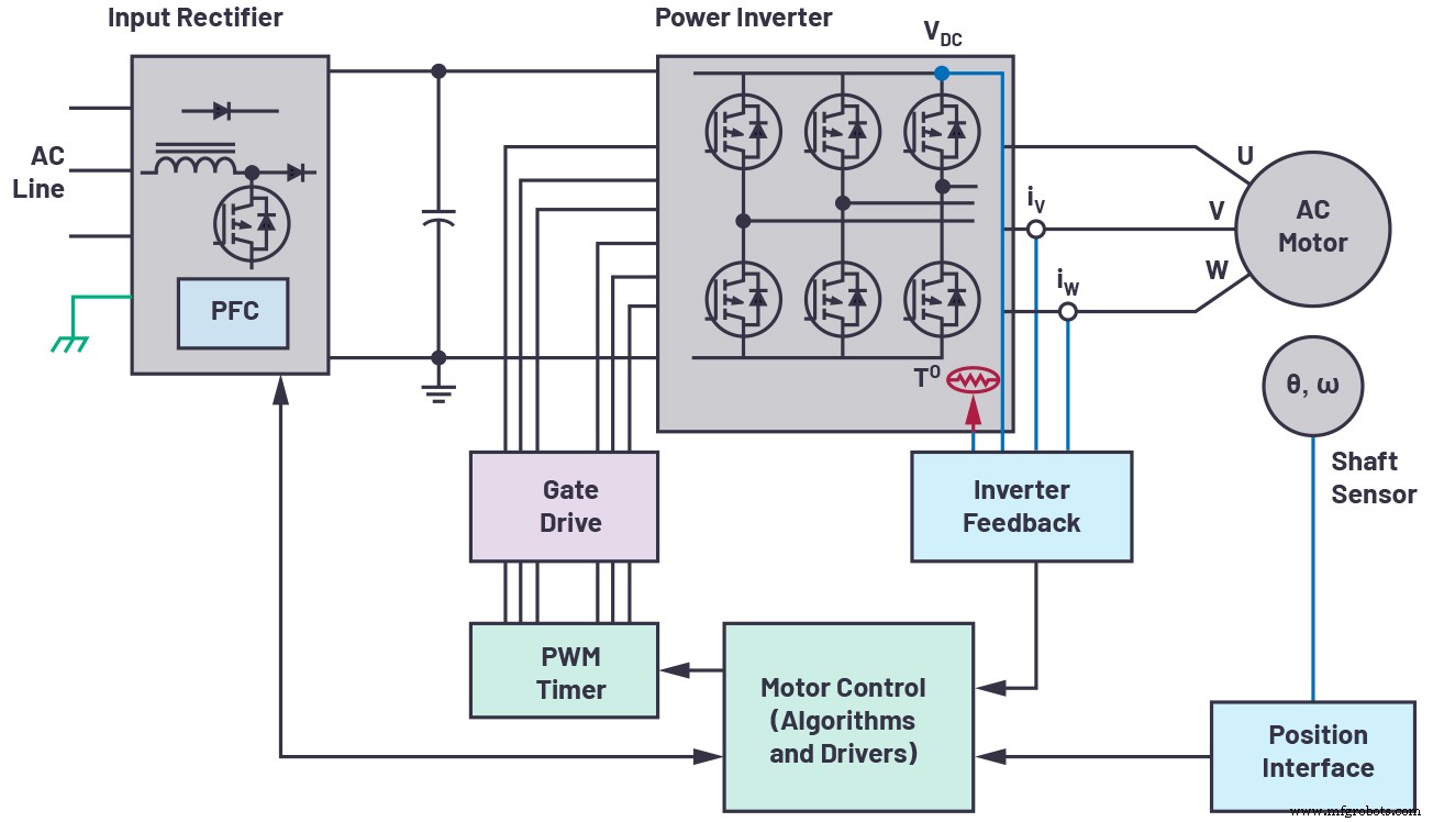
Figure 1. Closed‑loop motor control feedback system. (Source: Analog Devices, Inc.)
Motor Control Architecture
In a closed‑loop motor system, a motor, a controller, and a position‑feedback interface form the core loop (Figure 1). The motor converts electrical energy into mechanical rotation, the controller dictates acceleration, deceleration, and stopping points, and the position interface reports real‑time speed and location back to the controller. Accurate position data is the lifeblood of tasks such as precise component placement on PCBs and high‑speed pick‑and‑place operations.
For ultra‑small devices—robotic arms, micro‑assembly stations, and miniature actuators—every millimeter of PCB area counts. Thus designers must balance the stringent accuracy demands of the feedback sensor against the physical constraints of a tiny enclosure.
Position‑Feedback System Design
At the lower end, a simple incremental sensor paired with a comparator may suffice. High‑end applications, however, require a sophisticated signal chain: sensor, analog front‑end, ADC, and digital driver. Among these, the optical encoder remains the gold standard for resolution and robustness.
An optical encoder typically comprises an LED light source, a marked disc attached to the motor shaft, and a photodetector. The disc’s opaque/transparent pattern modulates the light, producing sine and cosine waveforms that encode the shaft’s absolute position. These waveforms, often in the millivolt to microvolt range, are amplified to a 1 V peak‑to‑peak window to match the ADC’s input range, maximizing dynamic range.
Because the sine and cosine signals must be captured simultaneously, the ADC must support simultaneous sampling. The resulting data is forwarded to an ASIC or microcontroller, which queries the encoder every PWM cycle to drive the motor accurately. Historically, designers had to trade off ADC speed, channel count, and board footprint—constraints that are now being broken by modern integrated solutions.
click for larger image
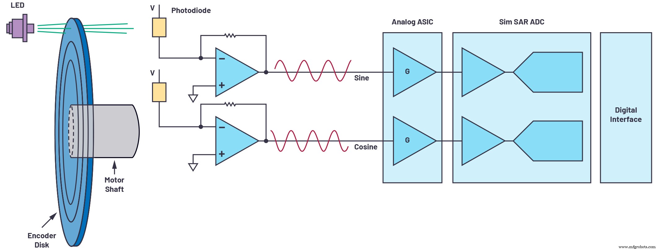
Figure 2. Position feedback system. (Source: Analog Devices, Inc.)
Optimizing Position Feedback
Contemporary motor control applications push the limits of encoder resolution. Modern optical encoders can feature hundreds or thousands of slots carved into the disc via fine lithography, enabling unprecedented precision.
By sampling the sine and cosine signals at a higher rate with a high‑performance ADC, designers can interpolate between samples, effectively increasing encoder resolution without redesigning the disc. Figure 3 illustrates how a slower sampling rate limits the fidelity of the position estimate, whereas a faster rate captures more detail and yields a more accurate shaft position.
click for larger image
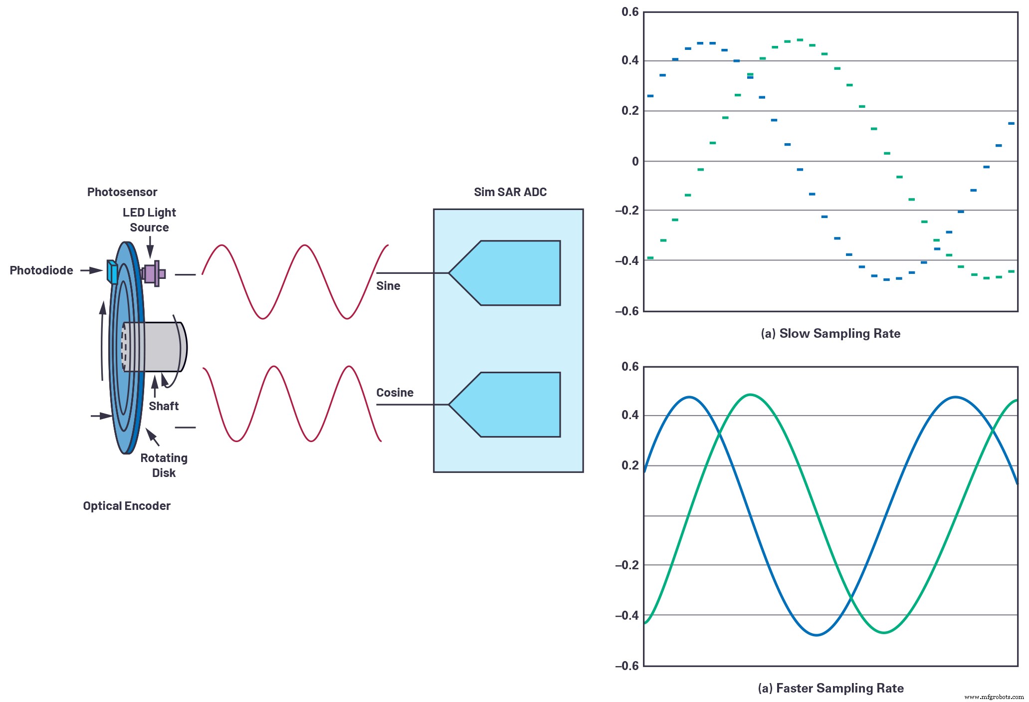
Figure 3. Sampling rate. (Source: Analog Devices, Inc.)
High‑speed sampling not only boosts resolution through oversampling but also relaxes the requirements on the downstream digital interface. A 4 MSPS ADC can deliver detailed samples at a lower serial data rate, simplifying the communication link to the controller.
Optical Encoder Position Feedback Design Example
The following schematic (Figure 4) showcases an optimized optical encoder interface for an absolute encoder. The front‑end uses an ADA4940‑2, a dual‑channel, fully differential amplifier that drives a 16‑bit, 4 MSPS, simultaneous‑sampling SAR ADC (AD7380) in a 3 mm × 3 mm LFCSP package.
click for larger image
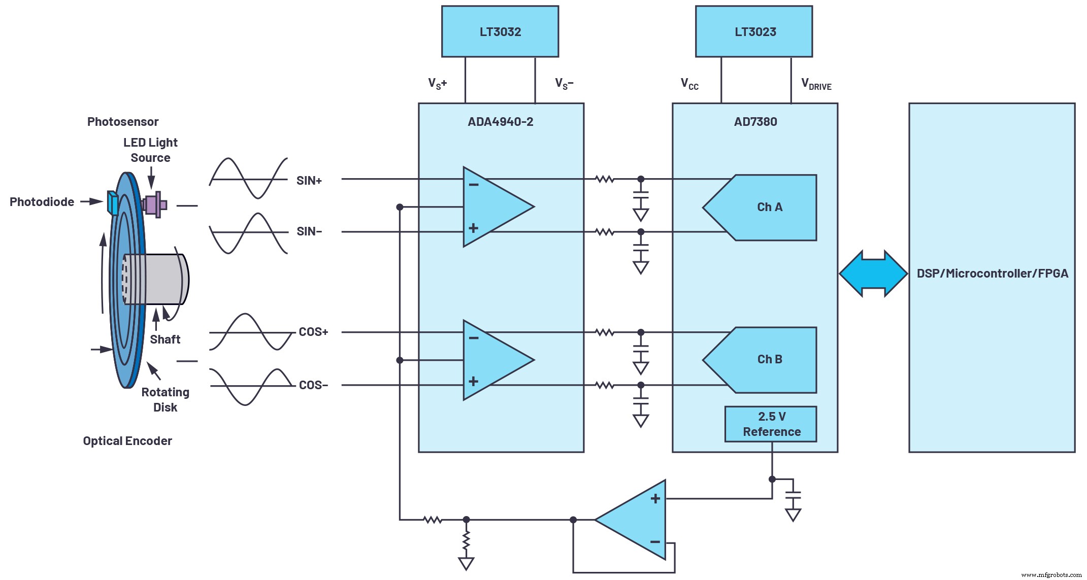
Figure 4. Optimized feedback system design. (Source: Analog Devices, Inc.)
The on‑chip 2.5 V reference eliminates the need for an external reference, reducing component count. A low‑dropout regulator such as the LT3023 or LT3032 supplies both the ADC’s VCC/VDRIVE and the amplifier’s rails.
When paired with a 1024‑slot encoder that generates 1024 sine/cosine cycles per revolution, the 16‑bit AD7380 samples each slot 216 times, effectively increasing the encoder resolution to 26 bits. The 4 MSPS throughput further enables on‑chip oversampling, which can add two more bits of resolution, reaching up to 28 bits with the ADC’s resolution‑boost feature.
In short, the combination of a high‑speed, simultaneous‑sampling ADC and a compact, fully differential front‑end transforms a standard optical encoder into a 28‑bit precision instrument—perfect for high‑speed, miniaturized motor control.
About the Author
Sensor
- COM‑HPC: The Next‑Generation Open Standard for Modular Embedded Systems
- Engineering Precise Motor Controls for Advanced Robotic Systems
- Advanced Ignition Systems for Reliable CubeSat Electric Propulsion
- Revolutionary Hypersonic Propulsion System Enables Sub‑30‑Minute Transcontinental Travel
- Choosing the Right Motor Sensor: A Guide to Accurate Feedback
- Advanced RFID Rotary Position Sensor for Precise Angular Tracking
- Building an Intelligent Compressor System to Boost Efficiency in Automotive Manufacturing
- Designing Your Compressor Room: 5 Essential Factors
- Expert Guide to Designing Efficient Compressed Air Systems
- Access Axis Current Position in Sinumerik 840D with the $AA_IM Variable