


Designing High‑Precision Continuous‑Wave ToF Systems: A Comprehensive Overview
Continuous‑wave (CW) time‑of‑flight (ToF) cameras deliver unparalleled depth accuracy, making them essential for modern machine vision, automotive safety, and consumer applications. This article introduces the core architecture of CW CMOS ToF camera systems and explains why they outperform traditional 3D imaging solutions. Future posts will dive deeper into the illumination subsystem, optics, power management, and depth‑processing algorithms discussed here.
Introduction
High‑resolution 3D depth imaging is now a prerequisite for safety‑critical machine vision. Reliable depth data ensures that robotic workcells and collaborative robots operate safely near humans, even in large, reflective spaces or amid moving objects. Traditional low‑resolution range finders cannot meet these demands. In contrast, CW CMOS ToF cameras offer the highest performance on the market, enabling applications such as video bokeh, facial authentication, driver‑alertness monitoring, and in‑cabin configuration.
Table 1. Continuous‑Wave Time‑of‑Flight System Features
| System Feature | Enablers |
|---|---|
| Depth precision & accuracy | Modulation frequency; modulation schemes; depth processing |
| Dynamic range | Readout noise; raw frame rate |
| Ease of use | Calibration procedure; temperature compensation; eye‑safety monitoring |
| Outdoor operation | Sensitivity at 940 nm; illumination power & efficiency |
| 2D/3D fusion | Pixel size; depth & 2D IR images |
| Multisystem operation | In‑pixel cancellation of interfering light; camera synchronization |
Continuous‑Wave CMOS Time‑of‑Flight Camera Overview
A depth camera measures distance by timing the round‑trip of light from an on‑board source to the scene and back. The sensor’s pixels record the return signal, and a phase‑based algorithm converts this into a depth map.
click for full size image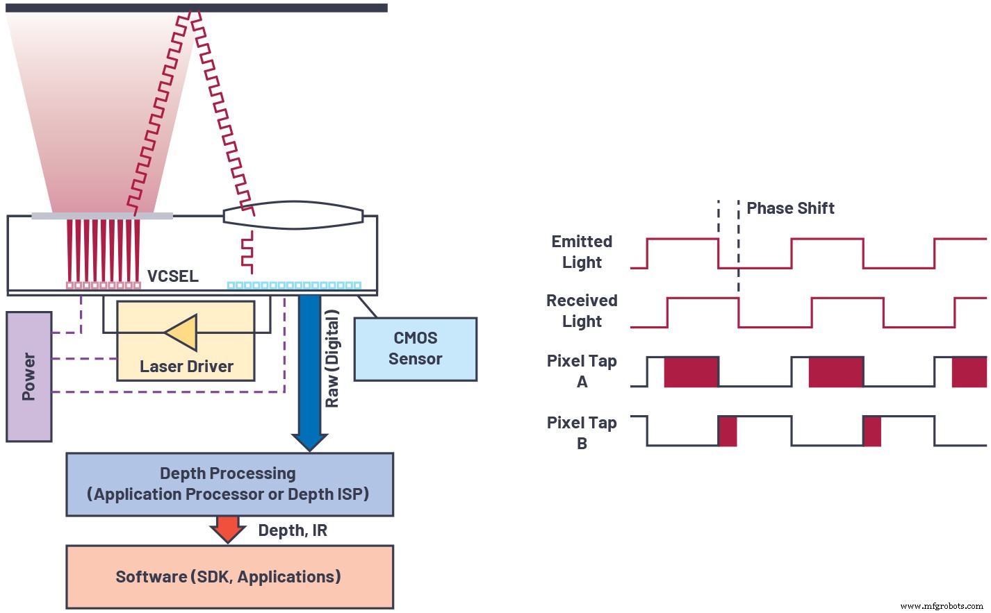
Figure 1. Overview of continuous wave time of flight sensor technology. (Source: Analog Devices)
A typical CW ToF system comprises:
- A near‑infrared light source (VCSEL or edge‑emitting laser diode) at 850 nm or 940 nm, usually flood‑illuminated.
- A laser driver that modulates the source at high frequencies.
- A CMOS sensor with a pixel array that demodulates the return signal.
- A lens and a narrowband filter to reject ambient light.
- Processing logic that extracts depth from the raw frames.
Modulation can be continuous‑wave, often approximating a square wave with a 50 % duty cycle. While square waves improve signal‑to‑noise ratio, they introduce high‑frequency harmonics that can bias depth. The camera measures the phase offset ϕ between transmitted and received signals, then calculates depth as:

High modulation frequencies reduce the impact of photon shot noise, readout noise, and multipath interference, thereby lowering depth error (see Figure 2). However, they also shorten the unambiguous range because the phase wraps more quickly. Multi‑frequency phase unwrapping—using one low‑frequency wave for large range and several high‑frequency waves for precision—overcomes this trade‑off (Figure 3).
click for full size image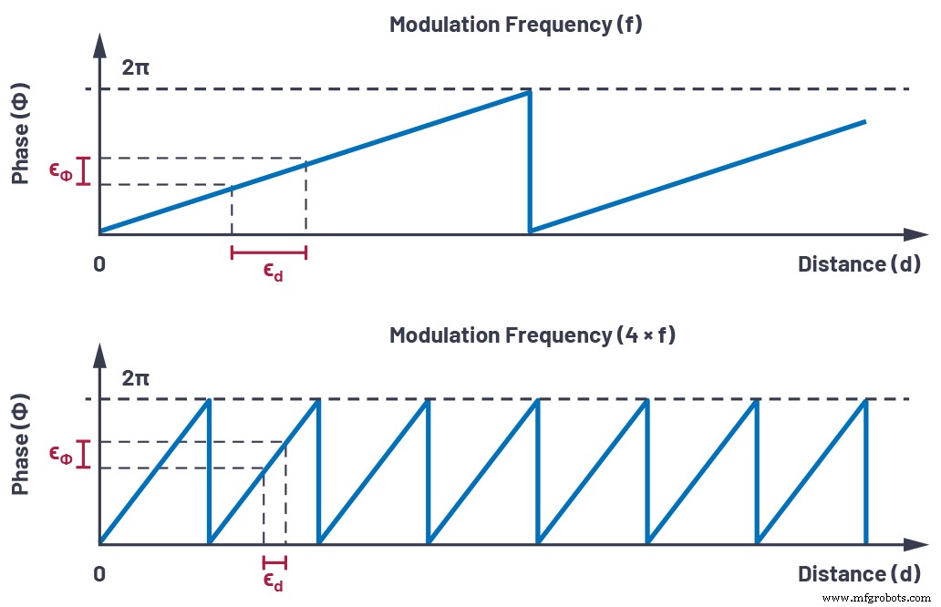
Figure 2. The effect of phase error on distance estimation. (Source: Analog Devices)
click for full size image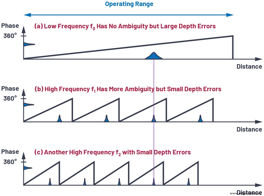
Figure 3. Multi‑frequency phase unwrapping. (Source: Analog Devices)
Choosing optimal weights for each frequency makes depth noise inversely proportional to the root‑mean‑square of the chosen modulation frequencies, allowing reduced integration time or illumination power for a given noise budget.
Other System Aspects Critical to Performance
The following components must be engineered for peak performance:
Image Sensor
High demodulation contrast at hundreds of MHz, high quantum efficiency at 850/940 nm, and low readout noise are essential for depth precision.
Illumination
Fast rise/fall times, clean waveforms, and Class‑1 eye‑safety controls ensure maximum usable signal and compliance with safety standards.
Optics
A low chief‑ray‑angle, high‑aperture lens paired with a narrowband filter maximizes light collection and suppresses ambient light, critical for outdoor use.
Power Management
Regulators with low noise and good transient response deliver the high peak currents required for laser and pixel modulation without compromising battery life.
Depth Processing Algorithm
Robust noise filtering, phase unwrapping, and geometric calibration convert raw pixel data into accurate depth maps, point clouds, and auxiliary images (amplitude, confidence). These algorithms can run on‑module or on an external processor.
click for full size image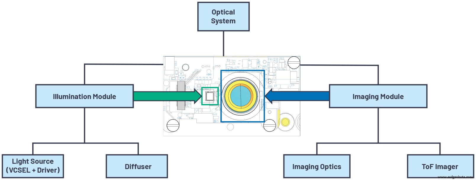
Figure 4. Optical system architecture. (Source: Analog Devices)
System‑Level Component Summary
Table 2. System‑Level Components of 3D Time‑of‑Flight Cameras
| Component | Key Features |
|---|---|
| ToF Imager | High resolution, high demodulation contrast, high QE, high modulation frequency, low readout noise |
| Illumination Source | High optical power, high modulation frequency, eye‑safety features |
| Optics | High light‑collection efficiency, minimal stray light, narrow bandwidth |
| Power Management | Low noise, good transient response, high efficiency, delivers high peak power |
| Depth Processing | Low power, supports multiple output formats (depth map, point cloud, confidence) |
Conclusion
Continuous‑wave ToF cameras are the premier solution for high‑accuracy depth imaging. By optimizing modulation frequency, sensor demodulation contrast, quantum efficiency, and readout noise, designers can achieve exceptional precision. System‑level choices—illumination, optics, power, and algorithms—must be equally meticulous to unlock the full potential of CW ToF technology. For detailed product information, visit analog.com/tof.
Authors

Paul O’Sullivan is a systems engineer at Analog Devices in Santa Clara, California. With a background in test development and advanced technology projects, he has led 3D ToF camera module development and calibration since 2019. Contact: paul.osullivan@analog.com.

Nicolas Le Dortz is the system engineering manager of the ToF Technology Group at Analog Devices. He directs cross‑functional teams to deliver high‑performance ToF camera systems. Contact: nicolas.ledortz@analog.com.
Related Contents
- Tools Move up the Value Chain to Take the Mystery Out of Vision AI
- Building effective IoT applications with tinyML and automated machine learning
- Time‑of‑flight technology promises enhanced accuracy
- Near‑infrared time‑of‑flight sensor reduces sunlight interference
- Lidar platform supports occupancy detection, social distancing
- ToF sensor offers fast 3D detection
- Ultrasonic time‑of‑flight sensor offers 1 meter range
For more Embedded, subscribe to Embedded’s weekly email newsletter.
Sensor
- Synchronizing Consistency in Industrial IoT: Choosing the Right Model
- Common Pitfalls in New Systems: How to Avoid Early Failures
- Designing Fail‑Safe Control Systems for Safety and Reliability
- STMicroelectronics Unveils Advanced Time‑of‑Flight Sensor for Precise Ranging
- Expert Guide to Planning & Designing Power Distribution Systems
- Smart Traffic Light Control System with Real-Time Data
- ToF vs. FMCW LiDAR: A Technical Breakdown for Informed Decisions
- Revolutionary Hypersonic Propulsion System Enables Sub‑30‑Minute Transcontinental Travel
- Optimizing Illumination Design for Robotic Surgery Vision Systems
- Is It Time to Upgrade Your Compressor? Spot the Signs Early