


Smart Lock & Sensor Design: Expert Circuit Protection & Sensing Strategies for Secure Smart Homes
This article offers a detailed exploration of access‑control architecture in modern smart homes and industrial buildings, focusing on the essential protection and sensing solutions that engineers must incorporate to deliver safe, reliable, and compliant products.
The convergence of smartphones, networking, and IoT has transformed the way we secure and manage our living and working spaces. By enabling real‑time monitoring and remote control, these technologies give homeowners and office occupants unparalleled convenience while enhancing perceived safety. Whether at home or on the go, users can effortlessly verify the status of locks, windows, and doors from anywhere.
Engineers who design smart locks, window sensors, and other security devices face a critical responsibility: they must avoid creating a false sense of safety. This requires a deep understanding of the protection and sensing components that not only meet safety standards but also ensure robust, dependable operation under real‑world conditions.
The smart lock market is expanding rapidly, with a projected compound annual growth rate (CAGR) of 25% that will push global shipments from roughly 7 million units in 2019 to about 23 million units by 2024 (Grandview Research, 2020). Residential installations will drive most of this growth, accounting for roughly 70% of total demand. Likewise, the window‑and‑door sensor market is expected to grow at a 9% CAGR, expanding from 300 million units in 2019 to 465 million units in 2024 (Outlook Market Research, 2019). These figures underscore the commercial opportunity for innovators who can deliver secure, high‑performance solutions.
Protecting Smart Lock Designs
A typical smart lock integrates a keypad, a wireless interface, a door‑handle position sensor, actuators for locking/unlocking, and tamper‑detection circuitry. Figure 1 illustrates a representative lock, highlighting the recommended protection and sensing components, while Figure 2 provides a detailed block diagram that shows optimal placement for these elements.
Electrostatic discharge (ESD) is the primary threat to lock electronics. Both the user interface (keypad) and the wireless interface can be exposed to human‑generated ESD, especially in dry environments. Shielding these circuits is essential to prevent damage to sensitive components.
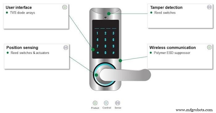
Figure 1. Smart lock with recommended protection and sensing solutions
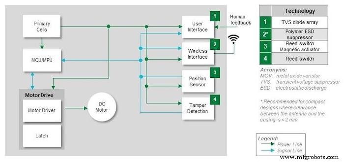
Figure 2. Block diagram of a smart lock showing circuit blocks and recommended protection components
For ESD mitigation, designers typically employ transient voltage suppressor (TVS) diodes or TVS diode arrays. A TVS diode array can protect up to five signal lines within a single 0402 surface‑mount package, delivering a minimum protection level of ±15 kV and a leakage current of only 1 µA. Figure 3 demonstrates a 5‑line TVS array, while Figure 4 shows a single‑line TVS capable of withstanding ±30 kV. Placement should be as close to the input of each signal path as possible to intercept ESD transients before they reach downstream circuitry.
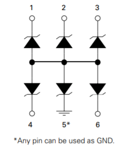
Figure 3. Example 5‑line TVS diode array
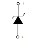
Figure 4. Single TVS diode with ±30 kV rating
The wireless interface, whether it connects to a cellular network or Wi‑Fi, is exposed to environmental ESD. Polymer ESD suppressors are ideal for this application because they offer fast response (<1 ns), negligible impact on signal impedance, and robust protection (±8 kV direct contact, ±15 kV airstrike). Typical capacitance is 0.06 pF. As illustrated in Figure 5, a bi‑directional polymer suppressor placed immediately adjacent to the antenna connector provides comprehensive shielding.
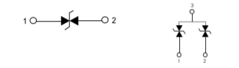
Figure 5. Bi‑directional polymer ESD suppressor configurations
Sensing Recommendations for Smart Locks
Ensuring that a door is fully seated requires a reliable proximity sensor. A reed switch paired with a magnetic actuator offers a low‑power, hermetically sealed solution suitable for battery‑operated locks. Reed switches can handle up to 10 W (0.5 A) and 200 V, making them ideal for low‑voltage control circuits. A cylindrical AlNiCo magnet (as small as 5 mm × 25 mm) provides the necessary magnetic field for the switch.
Similarly, tamper detection benefits from a reed switch–actuator pair. Because these components consume virtually no power, they extend battery life and can be fine‑tuned for sensitivity to detect unauthorized manipulation promptly.
By incorporating just four key components—TVS array, polymer suppressor, reed switch, and magnetic actuator—engineers can achieve robust protection and sensing while preserving board space and minimizing cost.
Protecting Wireless Door and Window Sensor Designs
Wireless door and window sensors deliver real‑time status updates from any location. Figure 6 presents a typical hardware configuration, indicating the recommended protection and sensing components for each subsystem.
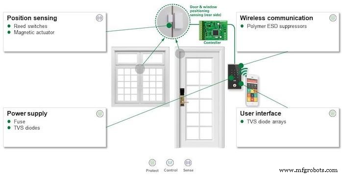
Figure 6. Wireless window and door sensor system with recommended protection and sensing components
As shown in Figure 7, the system comprises two main blocks: a battery‑powered sensor circuit on the door/window, and a fixed‑location user‑interface controller (typically AC‑line powered) that manages keypad input and RF transmission. The sensor side uses a reed switch–magnetic actuator pair for proximity detection, preserving battery life. The wireless interface on both sides uses polymer ESD suppressors to shield RF signals, while the keypad interface on the controller incorporates a TVS array for human‑contact protection.
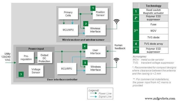
Figure 7. Block diagram of a door/window sensor system with recommended protection and sensing components
For the AC‑line powered controller, designers must guard against overcurrent, voltage spikes, and ESD. Time‑delay or slow‑blow fuses (with appropriate interrupting ratings) prevent nuisance tripping while accommodating inrush currents. Metal‑oxide varistors (MOVs) can absorb lightning or motor‑turn‑on spikes, handling up to 10 000 A from an 8/20 µs pulse and storing up to 530 J of energy. Alternatively, TVS diodes rated for lightning protection can dissipate 1 500 W from a 10/1 000 µs pulse with <1 µA standby current. Both components are available in surface‑mount packages to minimize assembly complexity.
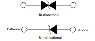
Figure 8. Bi‑directional and uni‑directional TVS diode configurations
Complying with Industry Standards for Electronic Security Products
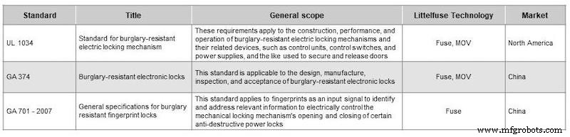
Knowledge of applicable standards is critical to avoid costly redesigns and launch delays. General safety requirements are outlined in the IEC 61000 series, covering ESD, fast transients, and lightning. Specific standards for electronic locks and related devices are listed in Table 1, covering the North American and Chinese markets. Referencing these documents during the design phase ensures compliance and builds trust with regulators and customers.
Table 1. Standards for Electronic Locking and Related Products for North America and China
Summary
Delivering a reputation for quality, reliability, and convenience is a powerful competitive edge for manufacturers of smart locks and door/window sensors. By integrating the appropriate protection and sensing components—TVS arrays, polymer suppressors, reed switches, magnetic actuators, fuses, MOVs, and TVS diodes—designers can achieve robust, standards‑compliant products with extended battery life and minimal board space. Leveraging the expertise of component suppliers and consulting their application notes further refines design choices and accelerates time to market.
For deeper insights into circuit protection, sensing devices, and component selection, consult the Circuit Protection Selection Guide and the Sensing Products Selection Guide from Littelfuse.
References
- Smart Lock Market Size. Grandview Research. February 2020.
- Window Sensors Market Outlook. Outlook Market Research. May 2019.
Industry Articles are a form of content that allows industry partners to share useful news, messages, and technology with All About Circuits readers in a way editorial content is not well suited to. All Industry Articles are subject to strict editorial guidelines with the intention of offering readers useful news, technical expertise, or stories. The viewpoints and opinions expressed in Industry Articles are those of the partner and not necessarily those of All About Circuits or its writers.
Automation Control System
- Designing Robust Circuit Protection, Control, and Sensing for Smart Home Security Systems
- Building Safe and Reliable Smart Power Outlets for Modern Homes
- Top Smart Home Upgrades to Modernize Your Living Space
- Top 13 Smart Home Devices & Systems of 2019 – Expert Picks
- Robust Automation & Cybersecurity: Complete Protection for Your Customers
- Circuit Protection: Key to Safe & Efficient Electrical Distribution Design
- Arduino Smart Home Automation: Circuit, Source Code & DIY Guide
- 7 Essential Tips for Designing Your First PCB
- Top 9 Tips to Optimize Printed Circuit Assembly and Reduce Costs
- Optimizing PCB Design for RF Circuits & EMC in the 4G Era