


Master Fusion 360: Leveraging Surface Modeling for Complex Geometry Machining
You are probably asking yourself “how can I use surfaces to machine other surfaces?!”. We know that a lot of the functionality within Fusion 360 can be underutilised by users. This may be down to lack of knowledge of each environment, or merely not knowing the benefits of utilising them in unison. For this reason, in this blog I will explain to you how to use surfaces to machine complex geometries, specifically to limit toolpaths.
Surface environment: Useful Tools
When it comes to using surfaces to machine complex geometries, many people are most concerned about the surface modelling steps required in order to achieve good results. Here’s a list of the commands I’ll be using (and why you should use them too!):
PATCH: The patch command will create a surface bound by an edge or a selection of edges. Simply select the patch command, select the edge(s) and a patch will form.
OFFSET: Offsetting a surface will create a duplicate of that surface at a given distance. In this case, you can use offsets to create duplicate surfaces without altering the solid model.
STITCH: Using the stitch command is not imperative, but will allow for easier application in the manufacture workspace. Stitching 2 surfaces will join them (assuming they intersect), allowing for a single selection when referencing them within your toolpaths.
Let’s now look at two specific examples.
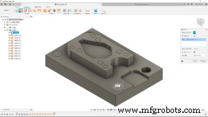
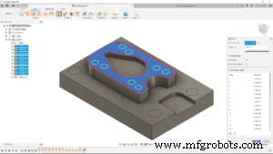
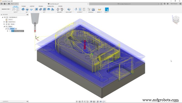
Surfaces to machine complex geometries: Holes on a prismatic, 2.5D Part
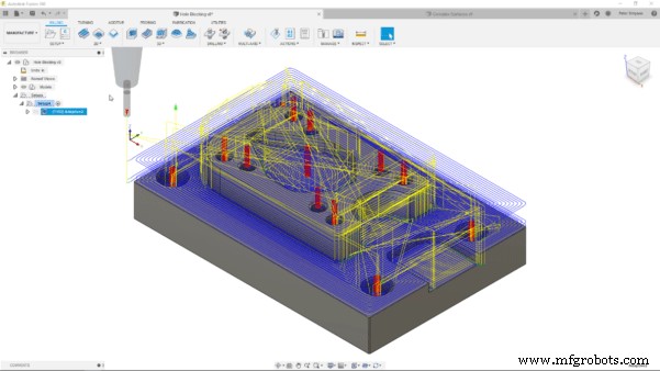
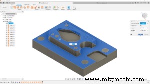
Let’s look at the model you can see above. I want to rough it using the 3D Adaptive Clearing toolpath. By default, the tool will try to enter the holes on the top faces. Unchecking the “Machine Cavities” box would help, but would not give me the flexibility I need. The surfaces you can see in the bottom image were created using the commands mentioned in the previous paragraph. I patched the holes, offset the faces and then stitched them together to create two surfaces, covering all the holes. Back in the Manufacture workspace, I can reference the surface within the geometry tab of the toolpath settings. By checking the box next to model and using the ‘Model Surfaces’ selection to select both surfaces, I have made the toolpath respect the surfaces and ignore the holes. I can then use a drilling operation to machine the holes.
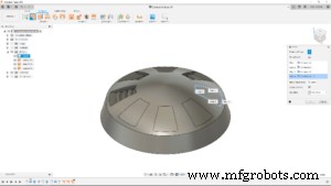
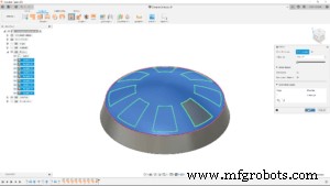
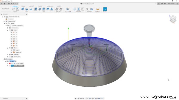
Surfaces to machine complex geometries: Avoiding Recesses
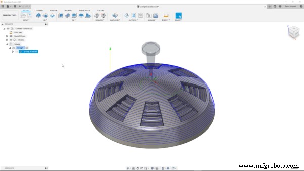
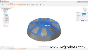
The model above features a circular pattern of recesses with complex surfaces within them. The dome-like top surface would ordinarily suit a scallop toolpath. However, the default toolpath morphs into the recesses, rather than giving the clean spiral I would expect. This would obviously lead to poor results and efficiency. To obtain the toolpath I had envisioned, I used the same workflow as before to patch, offset and stitch a continuous surface on that top face. This was then taken back into the manufacture workspace and referenced in the geometry tab of the toolpath settings. Those complex surfaces could then be finished with a smaller tool and finer stepover to obtain much better results.
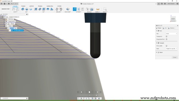
Bonus Tip: Using the Extend Function to Improve Edge Conditions
Here’s a little bonus workflow, again utilising surfaces, to improve machining outcomes even more! Due to the shape of a ball nose mill, machining will often leave ridges (cusps) on the machined surface. This will often happen at the edge of faces, as the toolpath will not account for the curvature of the end mill and just put the centre on the bottom edge, as you can see below.
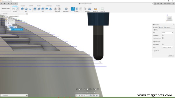
Luckily, you can easily extend a surface using the extend command, selecting the desired edge and inputting a value to extend it by. When I regenerate the toolpath, with the extended surface referenced as above, the toolpath will continue past that edge, removing the cusps. As a result, a much cleaner edge can be milled.
Conclusion
When using an integrated software such as Fusion 360, it is important to think about how to leverage tools in different, maybe even unconventional ways. Being able to use the Surface environment to easily create reference surfaces allows for greater control in the manufacturing process, without having to touch on much of the daunting, more complicated functionality. Hopefully this post has helped to refine your manufacturing workflow, enabling greater control.
If you want to work with more complex surfaces for machining, take a look at this Fusion Academy talk here. Are you new to Fusion 360 and want to try it out? You can download a free trial at this link.
Industrial Technology
- Leveraging Machine Learning for Enterprise Success
- Mastering CNC Milling: A Complete Guide to Operation and Setup
- Master Laser Cutting: Essential Tips & Step‑by‑Step Guide for Safe & Precise Operation
- Master Acrylic Cutting with a CNC Machine: A Step‑by‑Step Guide
- Mastering Compression Router Bits on CNC Routers: A Complete Guide
- Become a Machinist in Quebec: Path to a High-Demand Career
- Machine Parts with Fusion 360 Using a Generatively Designed 3D-Printed Fixture
- Master Fusion 360: Leveraging Surface Modeling for Complex Geometry Machining
- Master Fusion 360’s Machine Builder: Build Custom Machines for Simulation
- Pro Guide: Drilling Metal with Your Machine – Expert Tips