


Ferrite Core Transformers: Comprehensive Basics & Practical Guide
Most electric power transformers have secondary and primary windings as the basic features. Other times, there can be tertiary windings. As such, there should be an effective flux linkage amid the windings to drive the transformer. Consequently, there’s an addition of a low reluctance magnetic pathway of high proficiency to ensure the flux linkage works excellently. The magnetic path is what we refer to as a core.
Now, cores are of varied materials such as ferrites, steel, silicon, and many more. This article will focus solely on ferrite cores and expound on the different types, benefits, and applications. Additionally, we may give other knowledge that may be of importance to you.
1. What is a Ferrite Core Transformer?
Often, the magnetic ferrite cores have a combination of manganese, zinc, nickel compounds, and iron oxides. Since the compounds have low coercivity, they fall under soft ferrites. Ferrite core types comprise shell, toroidal, cylindrical, and closed-core.
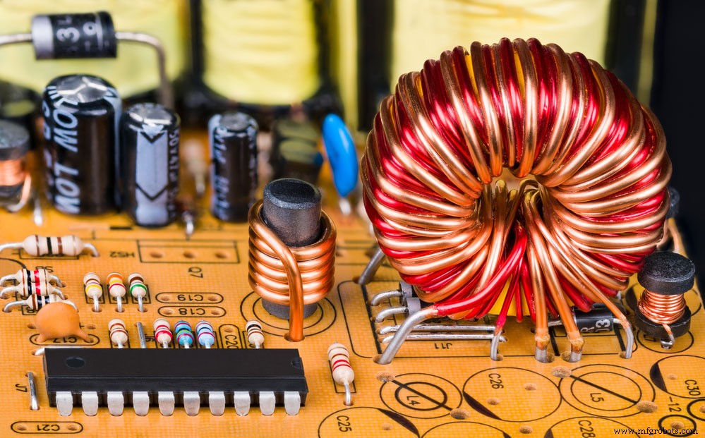
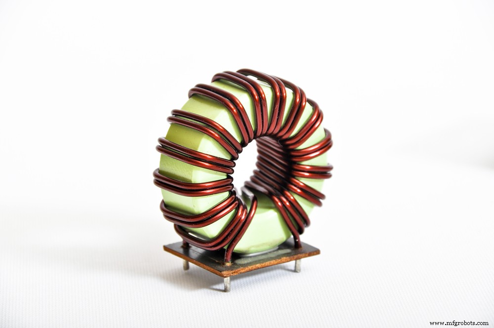
(toroidal or cylindrical inductors at the magnetic core)
Ferrite core transformers usually have a higher demand when compared to iron core transformers. The ferrite transformers have advantages, including resistance to elevated currents, low hysteresis losses, and no lamination required.
On the other hand, iron core transformers require lamination to attain a low eddy losses mode. Also, since you can’t thinner laminations, they tend to be ineffective for higher frequencies.
2.Ferrite Core Transformers Types and Benefits
Types
The list below comprises the major types of a ferrite core transformer.
Manganese Zinc (MnZn)
Besides an MnZn having a higher permeability, it also has a higher saturation level than a nickel-zinc ferrite. Therefore, they are best in applications that have a less than 5MHz operating frequency. In addition, the core’s impedance is suitable for inductors up to 70MHz.
Nickel Zinc (NiZn)
Compared to an MnZn, a NiZn has a higher resistivity. Because of that, you’ll mostly use it in applications that require a frequency range of 2MHz to several 100MHz. Moreover, its impedance can serve inductors that go beyond 70MHz. However, a NiZn ferrite core is temperature-sensitive with an even lower Curie temperature of under 500°C.
Sand Dust
Sand dust is a high-frequency choke coil that you can use only with a ferrite.
Lamination/ Amorphous & Nanocrystalline
Majorly, you’ll find the lamination/amorphous & nanocrystalline in areas such as UPS, welding sets, and inverters.
Also, it is good to note that ferrite cores come in different shapes as follows;
ETD cores; First, we have the ETD cores with minimum winding resistance at their center post. The winding resistance allows optimization of dimensions for increased power efficiencies. Furthermore, they suit inductors and power transformers efficiently.
EER cores; Secondly, there are EER cores with a round center post feature. Most times, the round center post will permit a shorter winding path length when compared to a square center post.
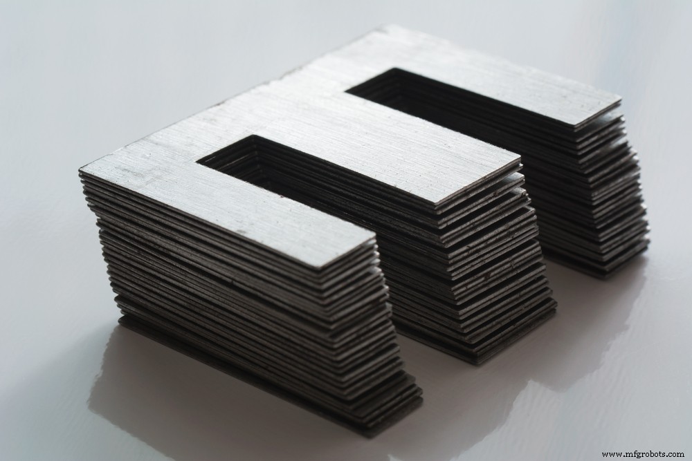
E, I core; Its feature is a bobbin winding. And you can assemble it with ease. E, I core uses are; inverter transformers, broadband, power, converters, telecom inductors, and differentials.
EFD cores; Have a cross-sectional area feature. Because of that, applications with several transformers & inductors and compact transformers can benefit from them.
(ferrite bead inductors).
Benefits
Some of the benefits of a ferrite core transformer offered for most electrical applications include;
- First, it is highly permeable to a magnet. Because of that, the transformer is often applicable in high-frequency transformers.
- Then, its electrical conductivity is low. This ensures the ferrite core doesn’t lose eddy currents.
- Also, the electric field intensity is higher. This enables a change in magnetic direction with slight hysteresis losses. What’s more, it’s good to note that hard ferrite cores have lesser coercivity than soft ferrite cores.
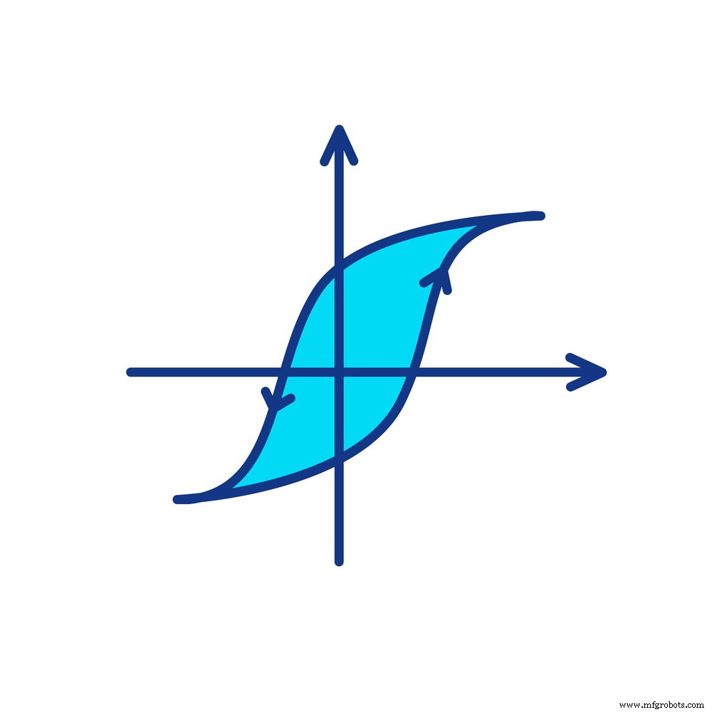
(hysteresis in a magnetic field).
Other benefits of ferrite core transformers in the electrical industry including;
- A low hysteresis factor,
- High Q values,
- Low signal distortion, and
- Low DC sensitivity.
3. What are Ferrite Core Transformer Major Applications?
A ferrite core transformer is in a wide range of applications that consist of the following;
- DC-DC converters; Here, they decrease or increase the Direct Current voltage.
- Mobile chargers; Evidently, each phone charger has a particular ampere and voltage. Hence, ferrite core transformers aid in stepping the voltage up and down as the requirement states.
- Power electronic circuits; All power electronic circuits with high frequencies integrate a ferrite core transformer. For example, there are pure sine wave inverters and switch-mode power supply inverters.
- Home appliances; A couple of home appliances that use the ferrite transformer include refrigerators, AC, washing machines, and TVs. Furthermore, the transformer helps in noise level suppression in EMI filtration as they operate.
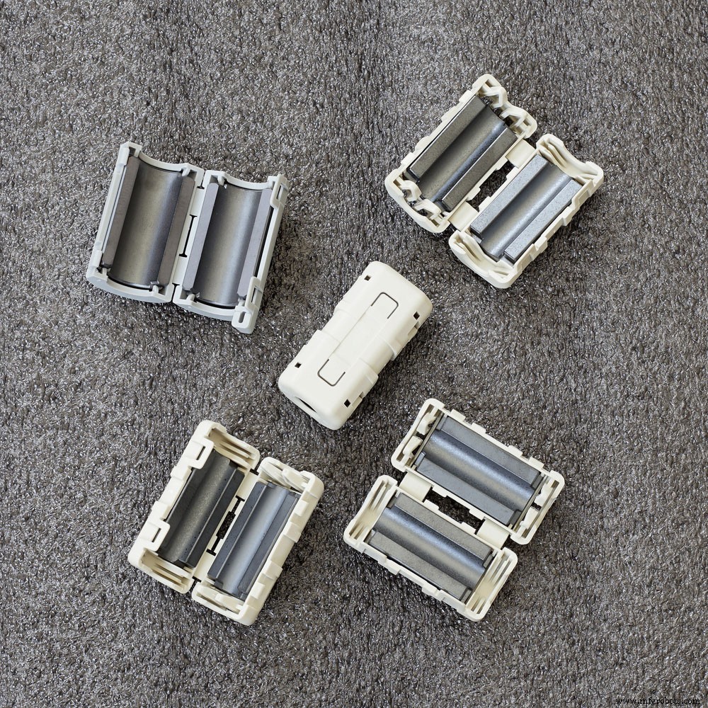
(noise reduction using ferrite components).
- Brushless DC inverters; Ferrite transformers convert an AC to DC or AC to AC in brushless DC inverter circuits.
- Solar panels; Further, in solar panels and batteries, the transformers increase the low DC voltage.
- Electric vehicles; Engine motors and chargers of electric vehicles use a ferrite core transformer.
- Lighting; Lastly, the ferrite transformers act as driver transformers and provide the required voltage in LED segments.
4. How to Calculate Ferrite Core Transformers
First and foremost, have all the required parameters in place. Our design here is a center tap push-pull topology.
Calculate primary turns
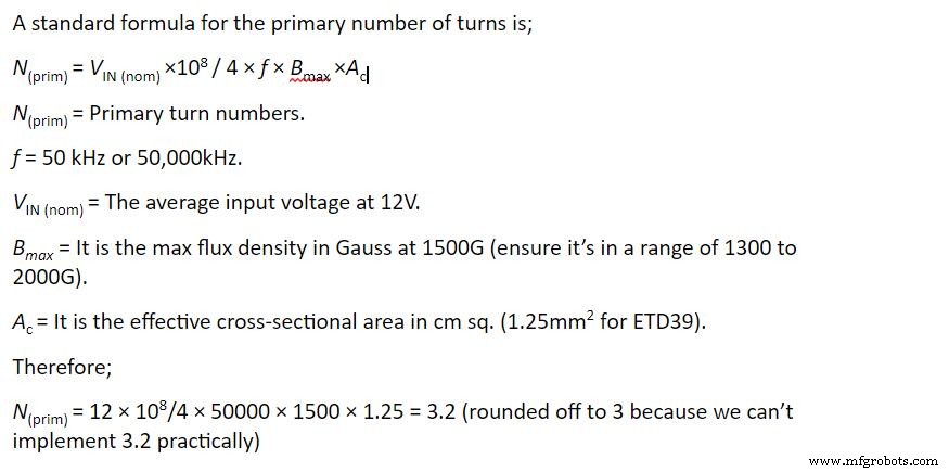
3 is the primary turn.
- Calculate secondary turns; Peak secondary value is constant at 310V. It helps in sustaining an operation voltage of 13V to 10.5V (lowest). An additional 20V to the 310V results in 330V, which is good enough for a maximum output peak voltage.
- Determine the maximum secondary voltage for PWM feedback control; PMW is 98% of the total duty cycle. So, when the battery is at 10.5V, 310V at secondary, we use the calculation; 98% × 10.5 V = 10.29V. The final maximum secondary voltage is at 330V while the primary voltage is 10.29V
- Find primary secondary turn ratio; Ratio is 330:10.29 = 32.1
- Calculating a secondary number of turns is found by multiplying the primary turns (3) and the ratio of voltage ratings (32.1). Now, 32.1 × 3 = 96.3 rounded off to 96.
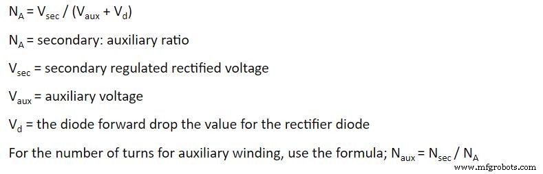
- Calculate the auxiliary number of turns
You’ll require the auxiliary winding for external implementation. The formula is as follows;
5. How to Design Ferrite Transformers of Various Topologies
Different applications and core types have varying names and topologies based on the circuit design. Some of the topologies include flyback, push-pull, half-bridge, and shell-type. Nonetheless, when designing any ferrite transformer with any topology form, consider the shape, unit cost, optimum temperature, size, and frequency. The mentioned points should uphold the transformer by minimizing core losses, providing electrical isolation, and preventing core saturation.
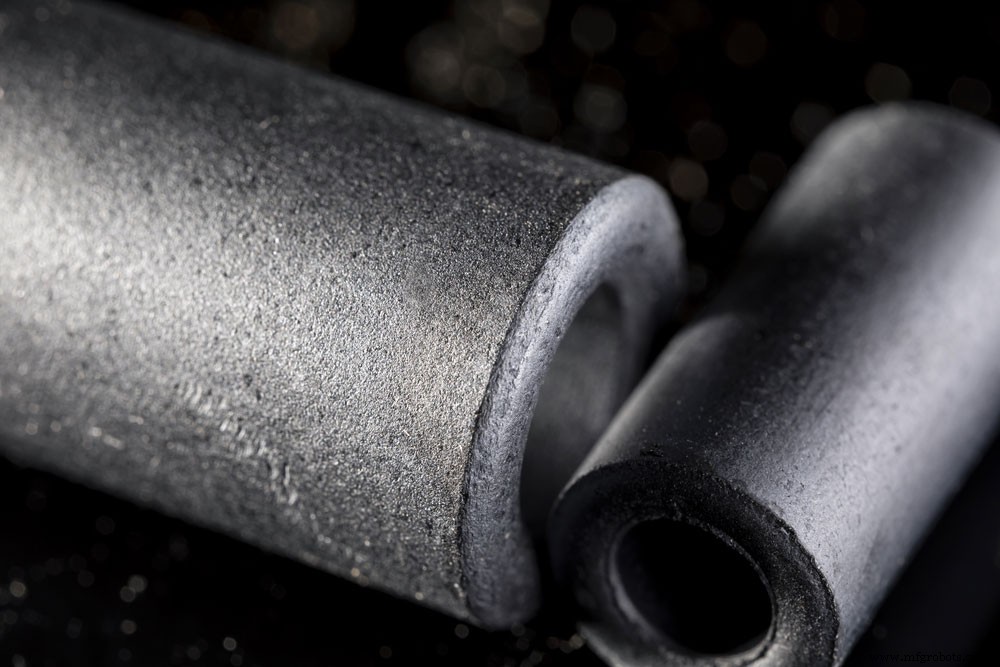
The operation frequency and size of ferrite transformers are dependent on two main applications; power and signal.
(ferromagnetic metal cores).
Signal applications; the ferrite transformer here has a high frequency ranging on a mega-Hertz scale and is small-sized.
Power applications; contrary to signal applications, the transformers here are large and of low frequencies (range – 1kHz to 200kHz)
Steps
- Before beginning your transformer design process, ensure your requirements align with the desired application. Project requirements may include current level, output voltage, operation frequencies, and input voltage.
- Secondly, check other parameters including operation temperature, mounting style, isolation, spacing, leakage currents, and size.
- Then, proceed to core selection. You’ll need bobbins to fit the core of your choice, and they also help in mounting your product once you finish it.
- Fourthly, using the formulae under the subheading ‘how to calculate ferrite core transformers,’ calculate the power losses, number of turns. Also, you can calculate other necessary parameters.
- Next, you need to determine the sire size and primary winding current.
The formula is – Primary current = total output power + transformer power losses divided by primary voltage.
- Afterward, determine the number of turns the secondary winding needs. Here, you’ll check the wires from your mechanical drawing. Then, ensure they fit into the winding area in the mean length of turns, height, and bobbin. Further, add some insulation between the windings but also consider the total winding height.
- In addition, measure the loaded voltage and open-circuit crossway the secondary winding to verify your design. Again, use the formulae in subheading four to calculate the resistance of each winding. Also, calculate the voltage drop crossway on the same winding. Voltage drop= current × resistance.
- Finally, finish by calculating the required temperature. Temperature rise in ferrite transformers results from winding power losses and core power losses. Depending on your application, the calculation should determine an acceptable temperature.
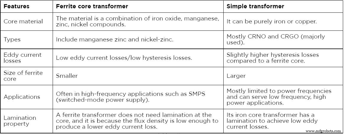
6. What is the Difference Between a Ferrite Core Transformer and a Simple Transformer?
The table below summarizes the differences between a simple transformer and a ferrite core transformer.
(copper coil transformer).
Conclusion
All in all, ferrite core transformers are the best option when considering high-frequency applications since they have efficient performance. The transformers have high magnetic permeability, high coercivity, and they conduct low electrical power. The high-frequency applications include switched-mode power supply, noise filters, RF (radio frequency) inductors, transformers, etc.
We still offer some guidance on how to go about using these transformers or buying the right one. In case you’rerenterested, you can reach out to us, and we’ll be happy to help.
Industrial Technology
- Choosing Between In‑House and Outsourced 3D Printing: A Practical Guide
- Understanding Stator Core Lamination: Key Concepts for Reliable Equipment Performance
- Industrial Wet Brakes Explained: A Comprehensive Guide for Reliable Heavy Equipment Stopping
- Master CMMS: Comprehensive Guide Part 2 – Essential Features for Efficient Maintenance
- CMMS Fundamentals: The Ultimate Guide – Part 1
- The Ultimate CMMS Guide: Part 4 – Choosing the Right System for Your Organization
- Back to Basics: The Ultimate CMMS Guide – Part 3: Selecting Features for Successful Implementation
- Mastering LED Strip Channels: Your Comprehensive Guide
- High-Current Voltage Regulator: The Complete Expert Guide
- Cold Electricity Explained: A Comprehensive Guide to LC Circuit Fundamentals