


VFD Schematics Explained: Circuit Diagrams, Types, and Building a Variable Frequency Drive
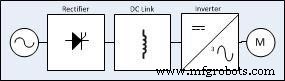
Every electronic enthusiast has come across the term VFD. VFD is the abbreviation for Variable Frequency Drive, also called Variable Speed Drives and Inverters. Its primary use is to manage the speed of an AC motor. Simply put, they are motor controllers that regulate the frequency and voltage served to the electric motor, based on its specific requirements. Generally, the three major components of a VFD schematic are the rectifier, the DC link, and an inverter.
Here, we explore the concept of the VFD bridge circuits, the different sections, types of VFD, and their advantages and disadvantages.
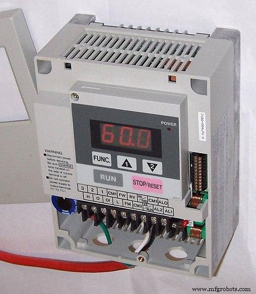
A Small Variable Frequency Drive
1. What is the VFD Circuit, and How Does it Operate?
As mentioned above, the Variable Frequency Drive makes an AC motor specification work at variable speeds. You should note that the AC motor alternates its speed by changing the voltage frequency used to run it. It implies that when you apply a voltage of 50Hz to an AC motor, the motor operates at a rated speed. However, if the input voltage you use exceeds 50 Hz, the engine runs faster than the rated speed. But if the voltage frequency you supplied is lower than 50 Hz, the motor operates slowly.
In line with the VFD working principle, the electronic controller alters the voltage frequency sent to the induction motor. With the invention of an advanced microprocessor, the VFD operates as a changeable device that controls the motor’s speed and guards it against overcurrent during workup and work down conditions.
The variable frequency drive circuit guarantees that excess current from the motor when operating, which helps keep utility costs down. Presently, you will notice that the VFD schematic is a popular type of output transistor used for a control system. This electrical device that transforms the AC power supply frequency, the VFD circuit, comprises three parts. These parts are a full-wave bridge rectifier, DC link, and an inverter.
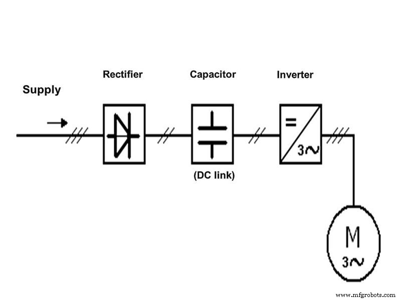
(The working principle of a Variable Frequency Circuit)
Basic Circuit Block Diagram of a Three-phase VFD
Three significant sections constitute the block diagram of a VFD. These sections include
- The power conversion area.
- The control section of the microprocessor is responsible for the control of the VFD operations.
- The power consumption section changes the AC voltage to DC. Also, changes the DC back to a 3-phase voltage.
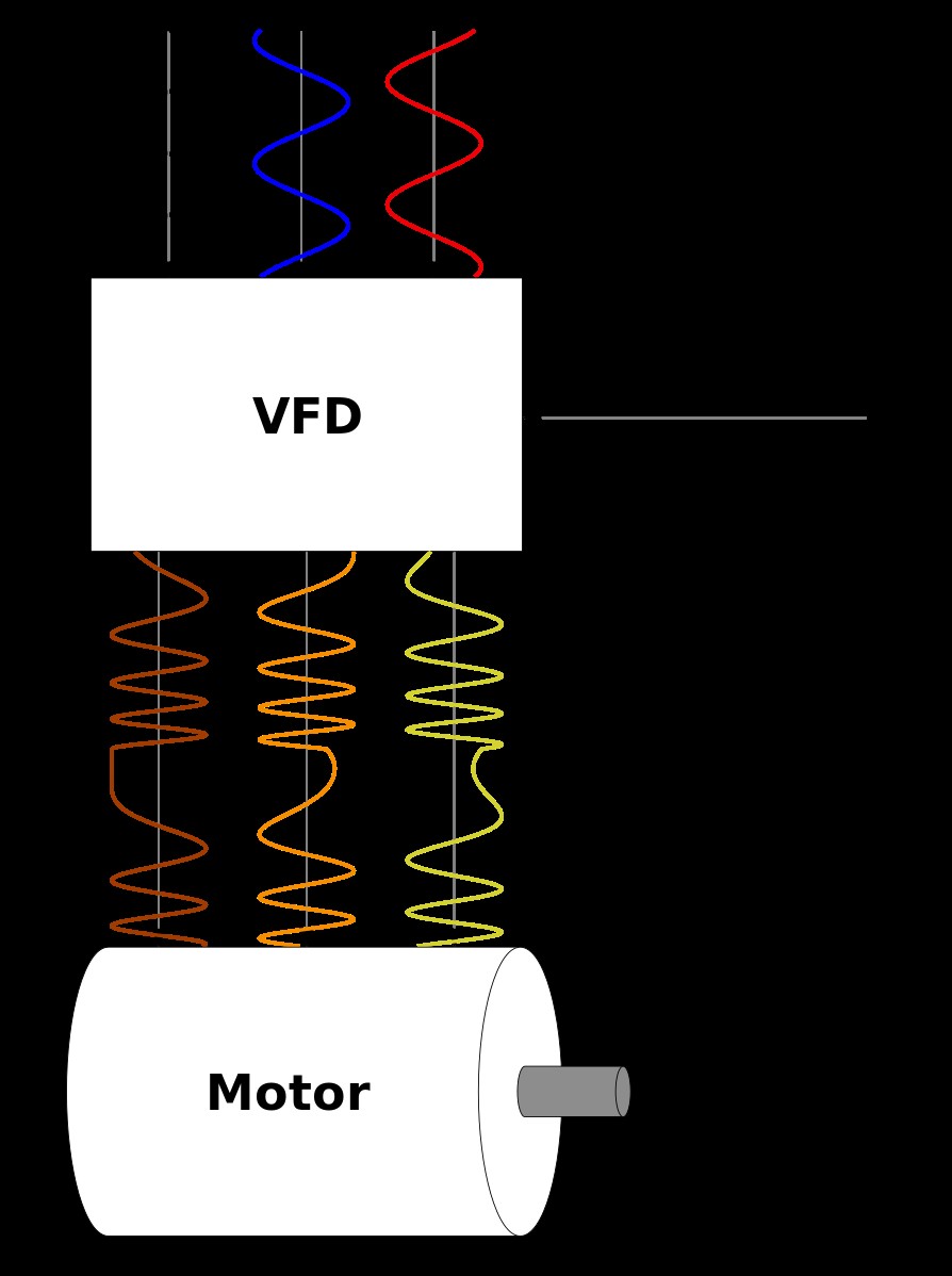
(A Three Phase Variable Frequency Drive)
The VFD circuit consists of three parts
Rectifier
It regulates the incoming three-phase AC power and transforms it to DC. Single-phase low-power VFDs possess single-phase rectifier circuits using diodes. Still, three-phase VFDs have three-phase rectifier circuits using SCRs because SCR is favorable for high positive voltages and high power applications.
DC intermediate circuit/ DC filter
The DC circuit delivers a smooth, improved DC voltage. Also, it is labeled as a DC-Link or DC Bus that comprises some capacitors and inductors. In this section of the VFD astable circuit, ripple segments from the output pins in the DC supply are eliminated.
Inverter
An inverter assists in rotating the DC on and off, which makes the motor acquire a pulsating voltage similar to AC. The alternation rate is controlled to alter the frequency of the simulated AC applied to the engine. It is vital, as the primary functioning of a VFD Circuit is dependent on this section, and VFD uses a full-controlled inverter circuit. In summary, with the controlled inverter circuit, the waveform of the output AC supply allows the motor to operate.
2. Different types of the VFD
Three main types of VFD are VSI, CSI, and PWM.
The VSI
Among these three, the VSI (voltage-source inverter) is the commonest of the types. The operation of a VSI requires the conversion of AC signal into DC by a simple diode bridge and a capacitor to reserve energy. The inverter then utilizes the reserved power to switch control to give the desired output. Undoubtedly, the use of the VSI comes with advantages and disadvantages.
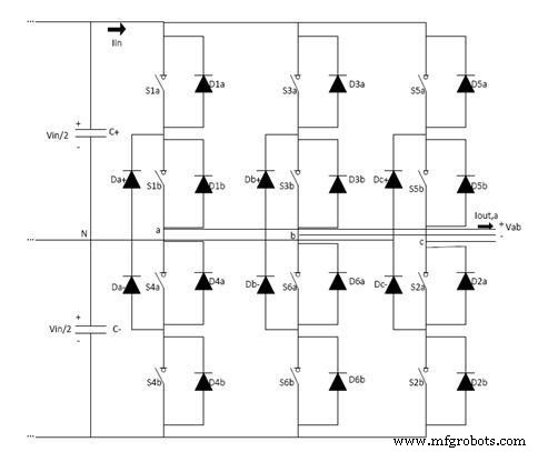
(A three-phase Voltage Source Inverter Circuit (VSI)
Advantages
- The production and installation of the VSI are cost-effective.
- In addition, it utilizes multiple motor control facilities which can connect with the single VSI type VFD.
- It possesses a good speed range.
- The design is simple and not complex.
Disadvantages
- The output frequency generates noises of different types.
- As a result of the cogging effect, the load motor face jerks during start and stop situations.
- Due to a controlled or decreased motor speed, resulting in a poor power factor.
Current source inverter (CSI)
The CSI (current source inverter), as opposed to the VSI, provides a smooth voltage output across pin3. The CSI type formation is dependent on current instead of voltage. Preceding, in the CSI, you can use the SCR bridge instead of the diode bridge rectifier. As an alternative to capacitors, we use inductors to analyze the output energy for smooth current output. Also, the CSI is capable of providing square waves of current.
(Current Source Inverter)
Advantages
- To begin with, it supports a higher horsepower induction motor where VSI is not adequate.
- It has higher reliability when compared to VSI.
- Above all, it possesses an excellent regeneration capability.
Disadvantages
- Most times, it generates a poor power factor.
- Also, it experiences a cogging effect that could shake the motor shaft when running.
- Lastly, it is not appropriate for multi-motor operation.
Pulse Width Modulation (PWM)
The PWM type ( pulse width modulation ) is also an improved version. With the PWM voltage-controlled circuit, the VFDs can give stable voltage output maintained with a frequency ratio. The PWM voltage controller circuit uses an additional regulator to provide the load’s steady and proper base supply voltage and current.
Advantages
- No clogging or jerking effect, and offers a wide speed and control knob range.
- Also, there is constant power with very high energy efficiency.
- It comprises different types of circuit protection.
Disadvantages
- There is some complexity concerning design and implementation.
- It generates disturbing noise in the phase driver circuit.
- Finally, it requires additional hardware and is a costly solution.
How to make a three-phase VFD circuit
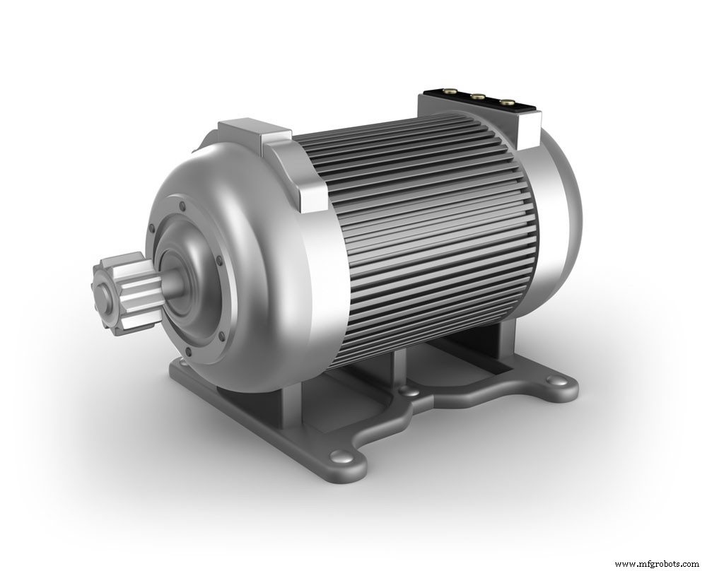
(An electric motor )
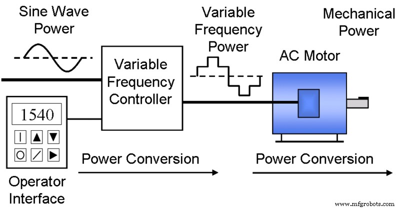
A typical Variable Frequency System Diagram.
We need the following to make a three-phase VFD circuit:
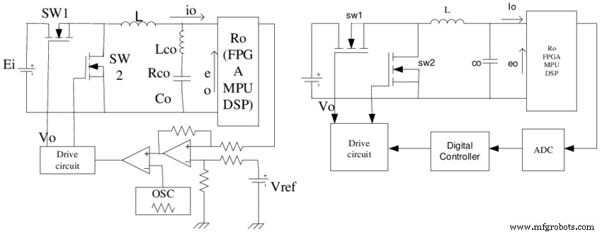
- PWM voltage controller circuit: The PWM generator stage generates a changing PWM output across pin 3 of IC2 in response to the voltage applied to pin 5 of the same IC.
- 3 phase H-bridge circuit: A 3 phase signal generating stage applies a well-calculated 3 phase signal across the IC’s HIN1/2/3 and LIN1/2/3 inputs.
- 3-Phase signal generator circuit: The input frequency of the three-phase signals determines the clocks sent into the system. Which usually, should be six times the intended three-phase signal. To put it another way, if the desired three-phase frequency is 100 Hz, the input clock should be 100 x 6 = 600 Hz.
- Voltage to frequency converter circuit for producing V/Hz parameter.
https://youtu.be/TAFDX301Qrk (Building a Variable Frequency Drive)
Conclusion
In all, for the additional control of the AC frequency converter circuit and the working of the AC motor at variable speed, we require the Variable Frequency Drive (VFD). The efficiency of the VFD solely depends on its type, range, and quality. Therefore, engineers should search for and utilize the very best for great results. Got any more questions concerning the VFD circuit configuration? Comment below or contact us.
Industrial Technology
- How to Build a Safe Taser Circuit: A Comprehensive Guide for Self‑Protection
- Tachometer Circuit Explained: Function, Design, and Build Guide
- Designing a Reliable Heat Sensor Circuit: Operation Explained & Step‑by‑Step Build Guide
- Speaker Crossover Wiring Guide: Types & How to Build Your Network Circuit
- Mastering the Emitter Follower Circuit: A Practical Guide to Impedance Matching and Current Gain
- Building a Crystal Oscillator Circuit: A Practical Guide for Engineers
- Reed Switch Circuit Explained: Principles, Applications, and DIY Build Guide
- Step‑by‑Step Guide to Building a Reliable DC Voltage Booster Circuit
- Silicon Circuit Boards: Advantages and Design Tips for Reliable Electronics
- Build a Pulsing LED Circuit: Step‑by‑Step Guide to Stunning Light Effects