


CD4060 IC: Comprehensive Guide to Operation, Applications, and Circuit Design
The CD4060 is an integrated circuit that belongs to the CD4000 series of integrated circuits. It contains an in-built oscillator that has the power to be set by a minimal number of external components.
We often use these essential components of the CD4000 IC series whenever using a microchip proves to be dangerous.
In this article, we will discuss the CD4060 integrated circuit in detail.

(different electrical components.)
What is CD4060?
A 14-bit binary counter integrated circuit with an inbuilt oscillator is the CD4060. This counter is usually a binary ripple counter carry type. The CD4060 is a complementary metal-oxide-semiconductor (CMOS) integrated circuit from the CD4000 family.
The I.C.’s primary use is to produce selectable time delays. Occasionally, you use it to generate signals of various frequencies. You can achieve this function because the integrated circuit CD4060 has an internal oscillator that requires only a few passive electronic components.
Moreover, if you are interested in making audio or a synthesizer, the CD4060 can help. For instance, this chip can create ten different frequencies from only a single capacitor and a pair of resistors.

(a printed circuit board)
CD4060 Pin diagram and pin configurations
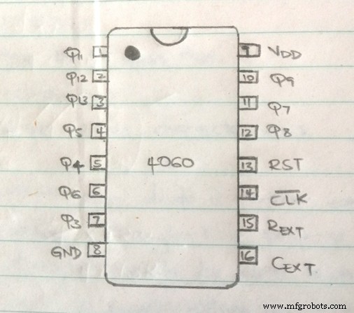
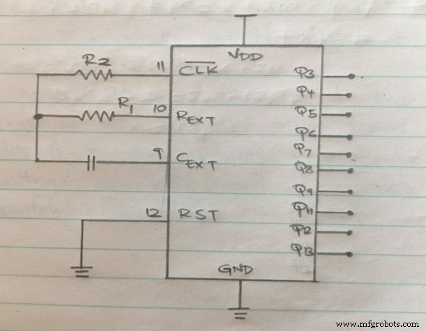
The CD4060 is a binary counter integrated circuit with 16 pins. From these pins, Q4 – Q14 are the output pins. On the positive edge of every clock pulse, the output pins produce a binary counter output. Otherwise, we use pin nine and pin 10 to connect the oscillator circuits.
CD4060 Pin diagram.
Below is a diagram representing the pin diagram of a CD4060.
(a cd4060 pin diagram.)
CD4060 Pin configuration
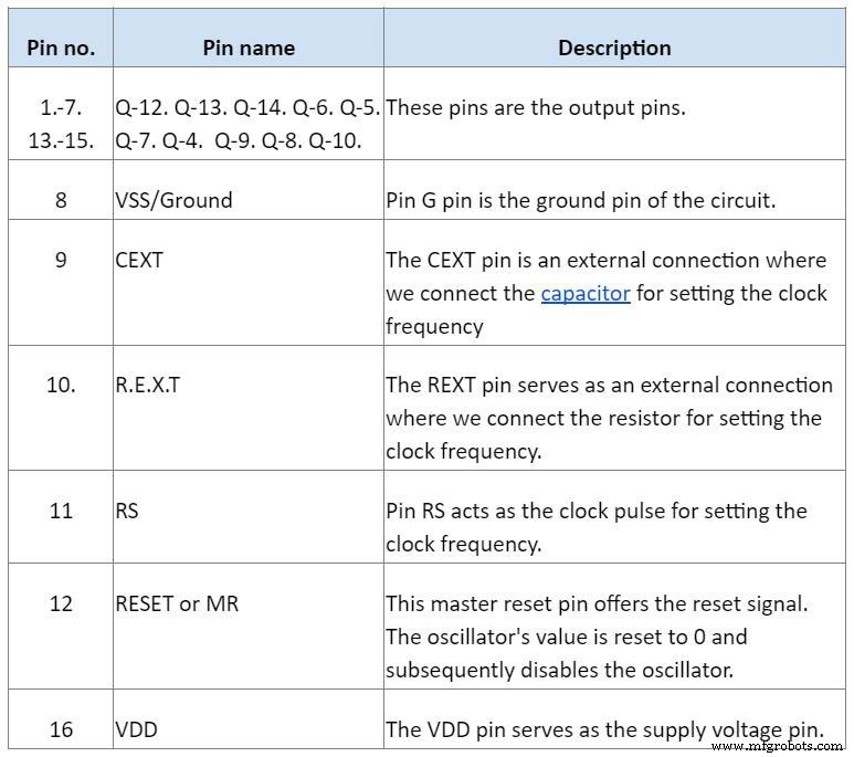
From a total of 16 pins, each pin has a name and description.
(a photo of a capacitor.)
CD4060 Binary Counter Feature
- First, this 14-stage integrated circuit is available in 16 pins PDIP, CDIP, SOIC, and TSSOP packages.
- Secondly, it has a reset propagation delay of 25ns at 5v.
- Next, the integrated circuit has a nominal voltage of 5v, 10, and 15v.
- The CD4060 has a counting range of 0-16383 (in decimal)
- Also, the integrated circuit has an operating voltage of between 3v-18v.
- Additionally, this binary counter with an oscillator has a maximum clock frequency of 30MHz at 15v.
- Moreover, this 14-bit binary counter IC has pins, and their function is compatible with that of the TTL series.
- In addition, the CD4060 IC operates under a medium speed of 8MHz type. At a VDD of 10v.
- Also, this integrated circuit has fully static operations with buffered inputs and outputs.
- Finally, this 16-pin PDIP has inputs that are Schmitt triggered to allow for the unlimited rise and fall times.

(image of computer circuits)
How Does the CD4060 IC Work?
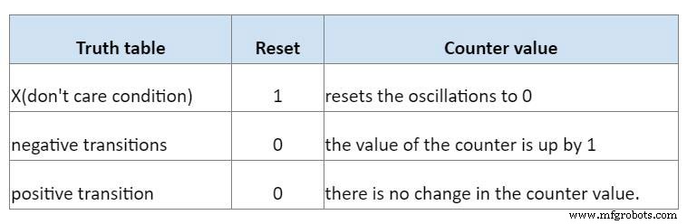
Since the Integrated Circuit CD4060 has a binary counter and an internal oscillator, it can transition on a clock pulse. For example, for every negative transition on a clock pulse, the resulting counter value increases by 1. Importantly, this figure is about binary numbers. Significantly, it would help if you always remembered to connect the reset pin to the ground or instead to the negative supply voltage.
Also, you can refer to the positive signal as a 1. Likewise, you can refer to it as HIGH. For instance, if you apply a high to the reset input, the reset pin immediately resets the oscillations to 0.
Below is a Boolean logic table that explains the RESET value and the clock pulse effects.
(an image of an electronic oscillator)
Alternatives of the CD4060
You can use the 7-bit and the12-bit CD4024B as alternatives to the CD4060. However, since the CD4060 belongs to the CD4000 series, you can use some I.C.s in this group as equivalents.
How do You Use the CD4060 IC?
To use this I.C., you need to power it via the V.S.S. and the ground pin. Also note, this I.C. has a wide operating voltage. However, the 5v supply is adequate. Significantly, it would help if you remembered to set your clock frequency.
You can set the clock frequency using F= 1 / (2.5*R1*C1). From this formula, you measure F in Hz, values of R1 in ohms, and C1 in farads.
Moreover, this I.C. has an internal clock oscillator. You can set this clock using an external resistor or an external capacitor. Furthermore, it would be best to remember that we use a pair of resistors and a single capacitor. Note that it connects one of the resistors from the R.E.X.T. pin to activate the counter. Then, click the other resistor goes from the CLK pin. The capacitor, on the other hand, connects to the C.E.X.T. pin.
(a Zener diode circuit.)
(5v battery power supply)
Similarly, when you vary the resistors and the capacitor values, you can get the clock pulses of different frequencies. After getting the vibrations, you can calculate the time using the formula T = 2n/F. Notably, in the formula, n is the number of outputs.
For example, with a resistor of 1MΏ and a capacitor of 0.22uF, you calculate frequency by substituting the formula values.
F= 1 / (2.5*1000000*0.00000022)
= 1.8 Hz
Similarly, to find a clock input when the output on Q5 is high, you substitute the values in the formula;
T = 2⁵/1.8
=17.75s
The calculations above explain that the output Q5 receives a positive signal after 17.7s of the counter I.C. reset.

(a technician is working on an electrical project)
Applications of the CD4060 IC.
- Firstly, this IC device is best to use in time-related applications.
- Moreover, we need this integrated circuit to create long periods in electronic systems.
- Also, we use this IC in projects where the presence of a microchip is dangerous.
(a microchip)
Summary
The CD4060 is a circuit that we utilize to acquire high-quality and precise frequency oscillations. It comes in handy when building a time delay circuit with minimal electronic components.
We hope this article has been of help to you. For any questions on this or any of our articles, kindly contact us.
Industrial Technology
- Master Social Media for Manufacturers: Comprehensive eBook Guide
- Design for Assembly: Enhancing Product Manufacturing Efficiency
- Integrated Circuits Explained: A Complete Guide for Engineers
- Digital Integrated Circuits: Types & Applications
- Mastering Opamp Hysteresis: A Comprehensive Professional Guide
- Master Class C Amplifiers: Comprehensive Guide & Expert Insights
- 556 Timer IC: Comprehensive Guide to Operation, Pinouts & Applications
- The IRF740 MOSFET: Comprehensive Overview & Practical Applications
- A4988 Stepper Motor Driver Pinout: Complete Guide to Features, Wiring, and Operation
- Determining if Your Part Is Ideal for 3D Printing: A Comprehensive Guide