


Arduino Breadboard: The Open-Source Solution for Efficient Prototyping
Prototyping is a big part of the design and development processes. It is essential before moving into more advanced phases in PCB projects. Therefore, if you are a digital electronics developer, an Arduino breadboard is the way to go.
Before Arduino, beginners had difficulty learning microcontrollers. They had to use expensive kits, which required assembly language coding that was difficult to use.
However, Arduino changed the game by providing an affordable, easy-to-use platform with coding in high-level programming languages like C++.
We will look into an Arduino breadboard and the steps required to make such boards.
What is Arduino?
Arduino is an open-source, digital electronics software and hardware platform, project, and user community. The platform designs and builds easy-to-use, single-board microcontrollers and their kits for developing digital electronics.
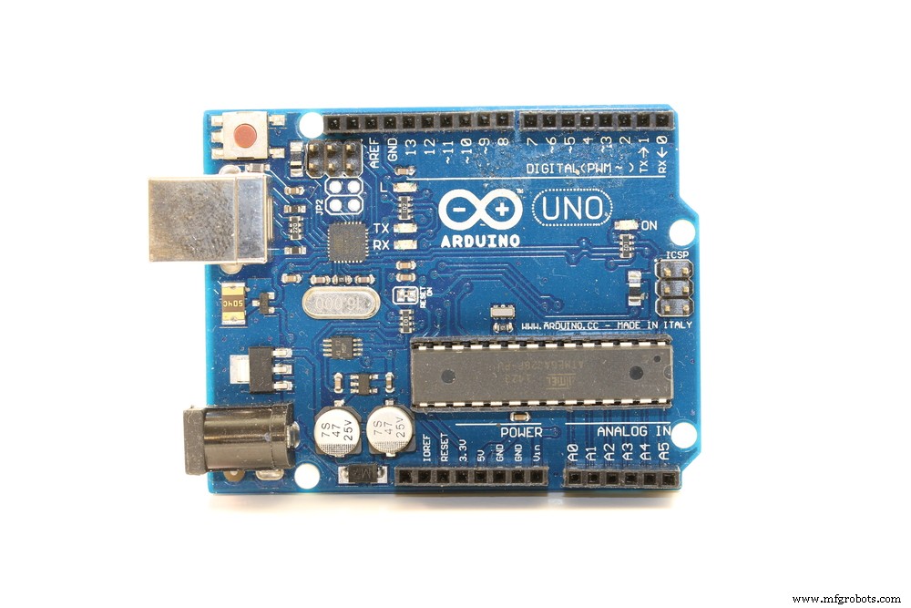
An Arduino circuit board
What is a Breadboard?
On the other hand, a breadboard is a rectangular plastic console with square perforated holes and symbols & lines engraved. It acts as a construction base to assemble multiple electronic components and microcontrollers like Arduino for prototyping purposes.
The breadboard’s solderless design is the main difference between it and PCBs.
A solderless breadboard
Usually, breadboards come with jumper wires, power supply units, and electronic components like transistors, resistors, and capacitors.
Some Specifications of Arduino
- Operating Voltage: 7-12V (DC jack), 5V (USB)
- Digital I/O Pins: 14 (6 for PWM operations)
- Analog Input Pins: 6
- Flash Memory for Program Storage: 32KB
- RAM: 2KB
- EEPROM: 1KB
- Clock Speed: 16MHz
- DC I/O Pin Current Output: 20mA
Building an Arduino Breadboard
When building an Arduino on a breadboard, a microcontroller, such as the ATmega328P, forms the barebones Arduino circuit kit. But the other parts are equally as important and make up the rest of the circuit. The specifications for the Arduino ATmega328P microcontroller are:
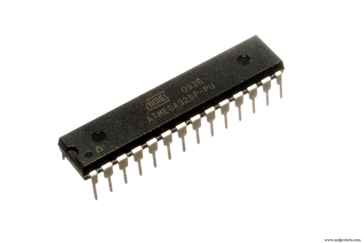
The ATmega328P chip
Source: Wikimedia Commons
Compared to the standard ATmega328p microcontroller, the breadboard Arduino option is better because it carries the Arduino bootloader. This bootloader allows for Arduino IDE programming. Also, breadboard Arduino will give you these advantages:
- A deeper understanding of how Arduino hardware works
- Easy scaling
- Low power consumption
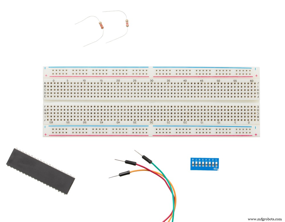
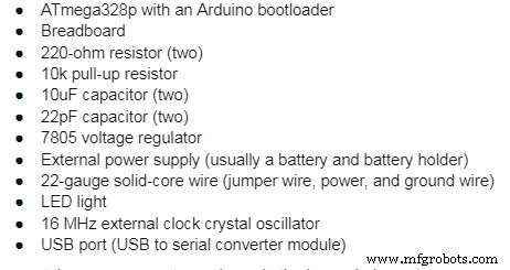
Required Components
To set up the complete project, you need the following components:
Connect these components as shown in the image below.
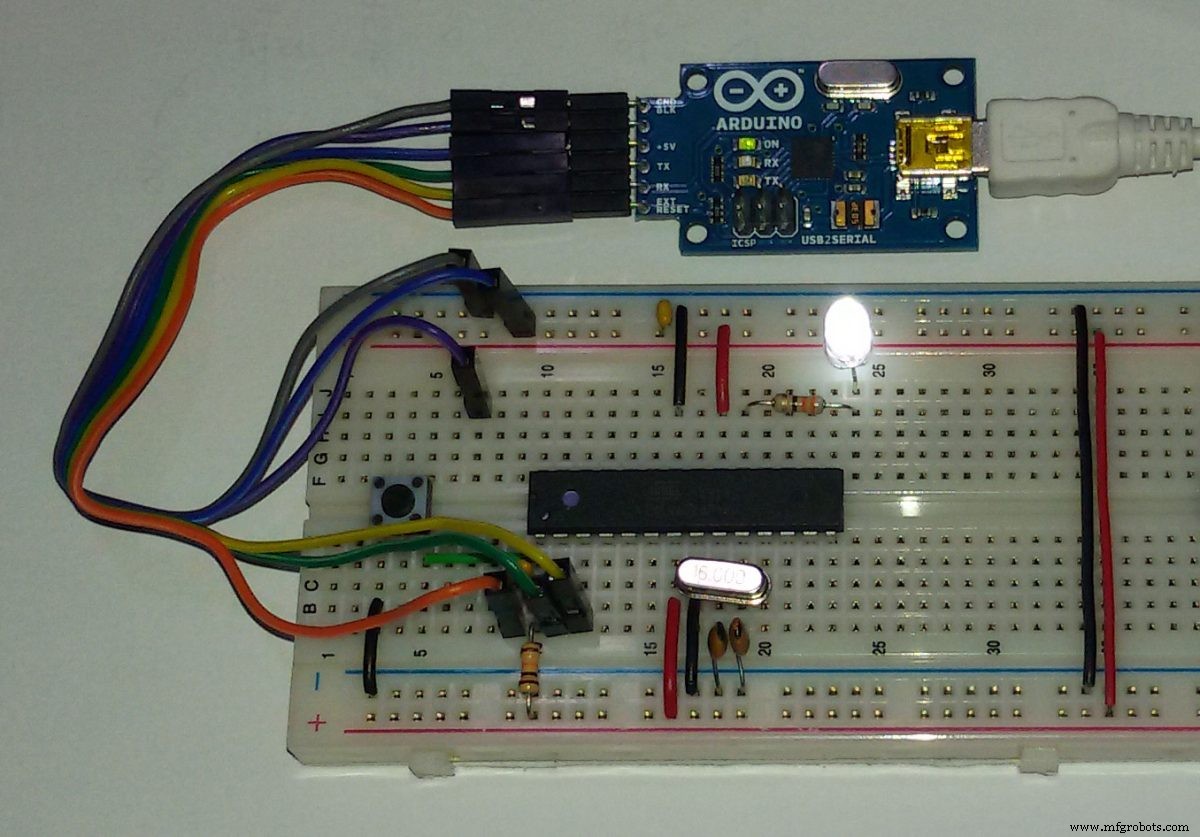
An Arduino ATmega328p breadboard with a USB-to-serial converter module
Source: Wikimedia Commons
To help you with the connections, you need to know what each pin is for in the microcontroller. Here is a pinout diagram for the chip.
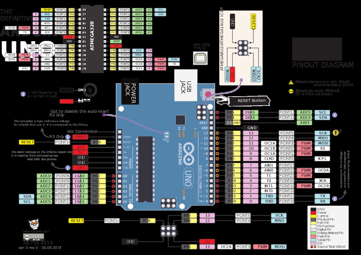
A pinout diagram of the ATmega328p and the Arduino board
Source: Wikimedia Commons
Connecting the External Power Supply
Begin by connecting the wiring for the breadboard power supply. The process involves fitting the power and ground wires where the voltage regulator will sit. Take note of the pin numbering to prevent any wrong component connection.
Next, add the ground and power wires at the bottom of the board to connect each rail. Afterward, attach the power regulator and power rails to the board.
The max voltage that you can apply to the VCC pin is 6V, and you should avoid getting to this value. Use between 3.3-5.5V.
In most cases, a 9-12VDC power supply (battery) is sufficient. However, this is the work of the voltage regulator. Therefore, the input power should be 7-16V to get about 5V from the regulator.
Add a 10uF capacitor between the regulators IN & ground. Also, fit a similar capacitor on the right rail between the floor and power.
Next, stick the LED light and 220-ohm resistor to the board’s left side, right across the voltage regulator.
Once you sort out the power source, it is time to load the microcontroller, then the USB to serial converter module.
Connecting the Microcontroller
First, plug the chip into the breadboard, as shown in the above image. Next, connect the 10k pull-up resistor to +5V from the reset pin to prevent chip resetting in regular operation. If ground to 0V, the reset pin reboots the microcontroller.
Next, attach the 16 MHz clock to pins 9 and 10. Connect the two 22 pF capacitors to each of these pins and the ground.
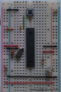
An ATmega328P chip attached to a breadboard
Source: Wikimedia Commons
After that, connect a small tactile switch between the reset and ground pins to act as a reset button. With this component in place, flip the switch if you want to restart the chip to upload a new program.
It is important to note that some chips come preprogrammed with the blink LED program. Usually, Arduino software contains the program straight from the manufacturer.
Ensure these pins connect as follows:
- Pin 7 – Digital supply voltage (VCC)
- The Pin 8 – GND
- Pin 20 – AVcc – ADC converter supply voltage. You should connect this to the input power if not using an ADC. If using an ADC, connect the pin to power via a low pass filter.
- Pin 21 – AREF – Analog reference pin for ADC
- Pin 22 – GND
The board LED should blink after setting up everything and connecting the battery. The purpose of the LED light is to check whether the board is getting the right amount of power or is shorting.
You can stop here, but the real fun comes when you program the Arduino breadboard. To flash it using your code, you need to connect the USB to serial converter module to the breadboard.
Since you will be typing the code on the Arduino IDE in your computer, the USB to serial converter module provides a USB port. It would help if you had the port to connect your computer to the breadboard chip via a USB cable.
Connecting the USB to Serial Converter Module
You only need to make these five connections:
- Rx to Tx
- Tx to Rx
- Vcc to Vcc
- GND to GND
- DTR/RTS to RST via the 10uF capacitor
From there, you can get creative on the Arduino IDE. Then try to run different pieces of code on the chip, such as going into sleep mode for a certain amount of time.
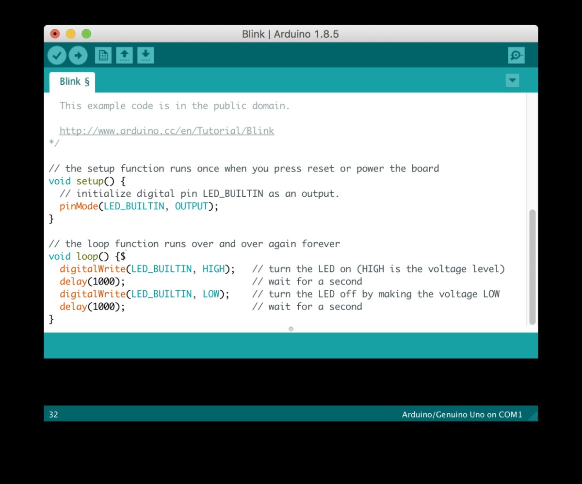
Sample LED blinking code on the Arduino IDE
Source: Wikimedia Commons
Summary
As you can see, Arduino breadboards provide an easy-to-use and affordable platform for testing and development, making it ideal for beginner digital electronics designers. If you have any questions, hit us up for further clarification.
Industrial Technology
- OpenDDS vs. RTI Connext DDS: Choosing the Right Data Distribution Service Solution
- A Beginner’s Guide to Open‑Source Terminology
- DeepLabCut: Open-Source AI for Precise Body-Part Tracking in Moving Animals
- DIY Arduino Word Clock – Build a Sleek Real-Time Display
- Build a Basic Calculator with Arduino UNO – Easy Project
- SerialDebug: Boost Arduino Debugging with Advanced Serial Logging
- Arduino UNO Breadboard Computer Programmer – Build & Code Your 8‑bit System
- DIY Open-Source Pulse Oximeter for COVID-19: Arduino Build
- Choosing the Right CMMS: Free, Open Source, or Trial Software Explained
- Arduino Boards Explained: A Complete Guide to Choosing the Right Model