


DIY Open-Source Pulse Oximeter for COVID-19: Arduino Build
Components and supplies
 |
| × | 1 | |||
| × | 1 | ||||
 |
| × | 1 |
Necessary tools and machines
 |
| |||
 |
|
Apps and online services
 |
| |||
 |
|
About this project
The Challenges of COVID-19COVID-19 is a disease caused by the SARS-CoV-2 virus that primarily attacks a person's respiratory system. Some milder symptoms can include fever, aches, and chills, but it can also lead to more serious conditions such as pneumonia. A person who has pneumonia or even slight shortness of breath might not know when to go to a hospital, especially as they start to get even more overwhelmed. This is why I created this open source pulse oximeter, which can assist in getting people the help they need and get accurate information about their current condition.
This device/project is not to be used as an accurate medical diagnostic tool!
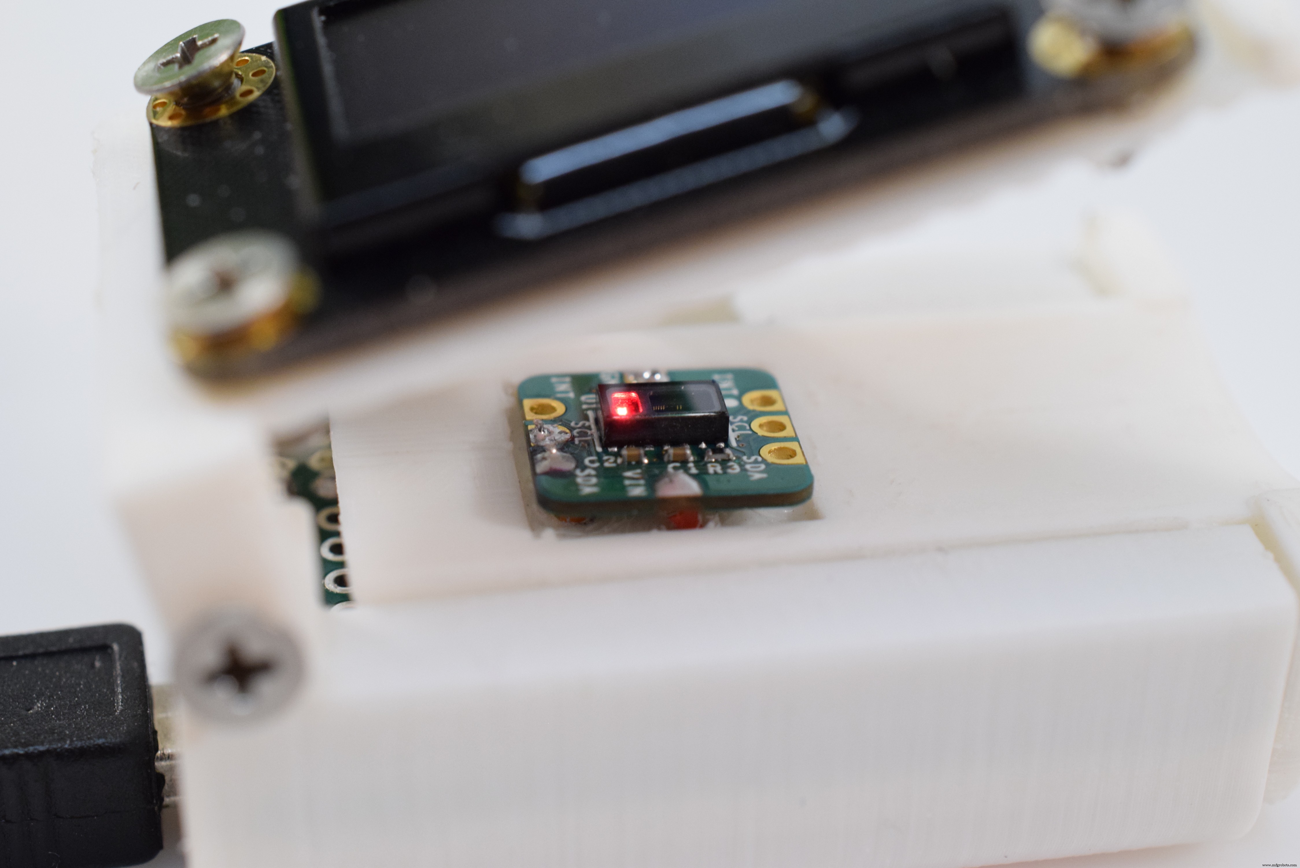
The ElectronicsMAX30102

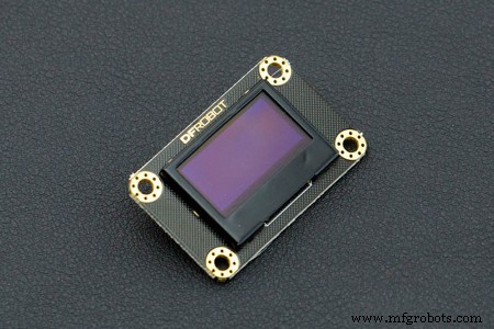
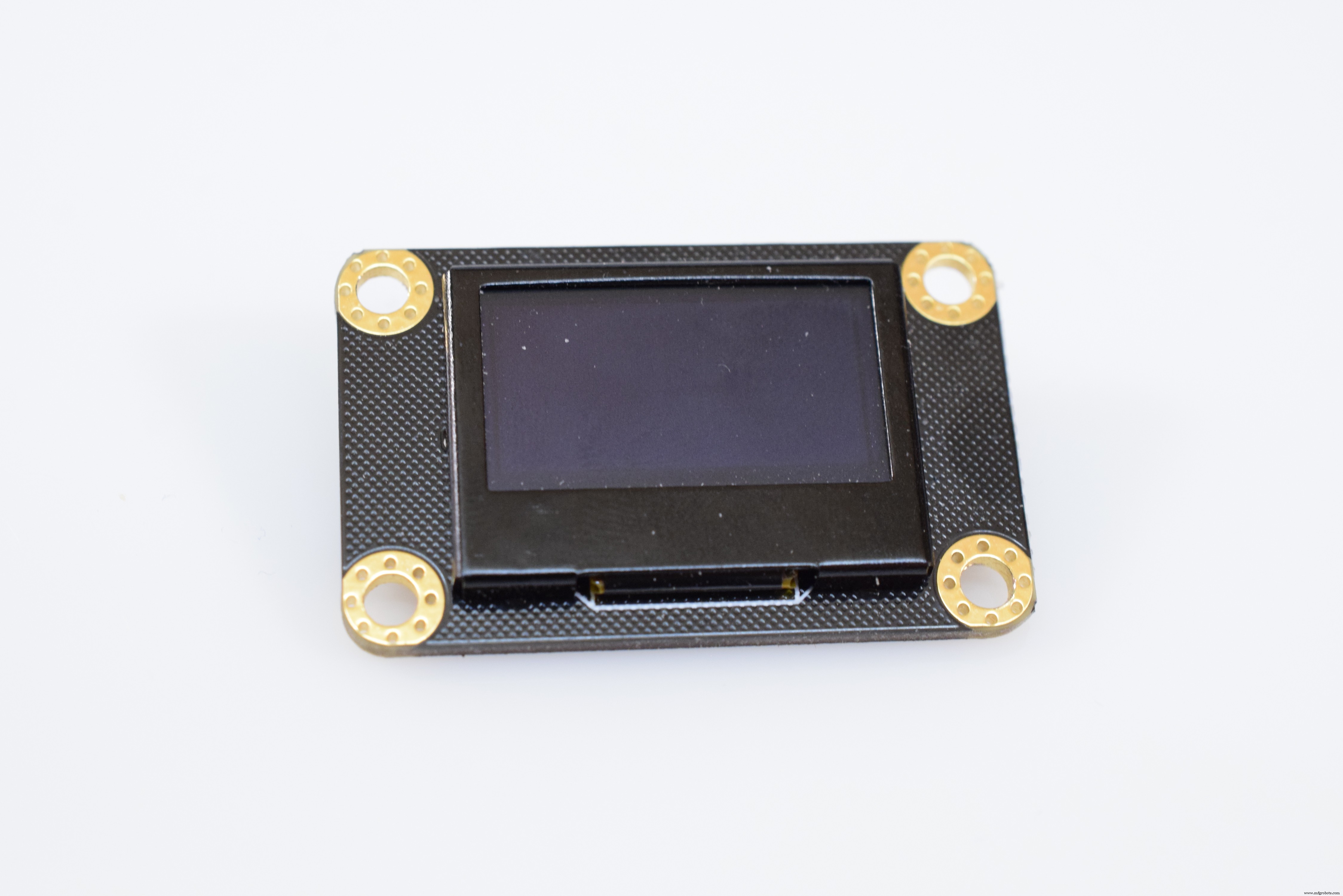
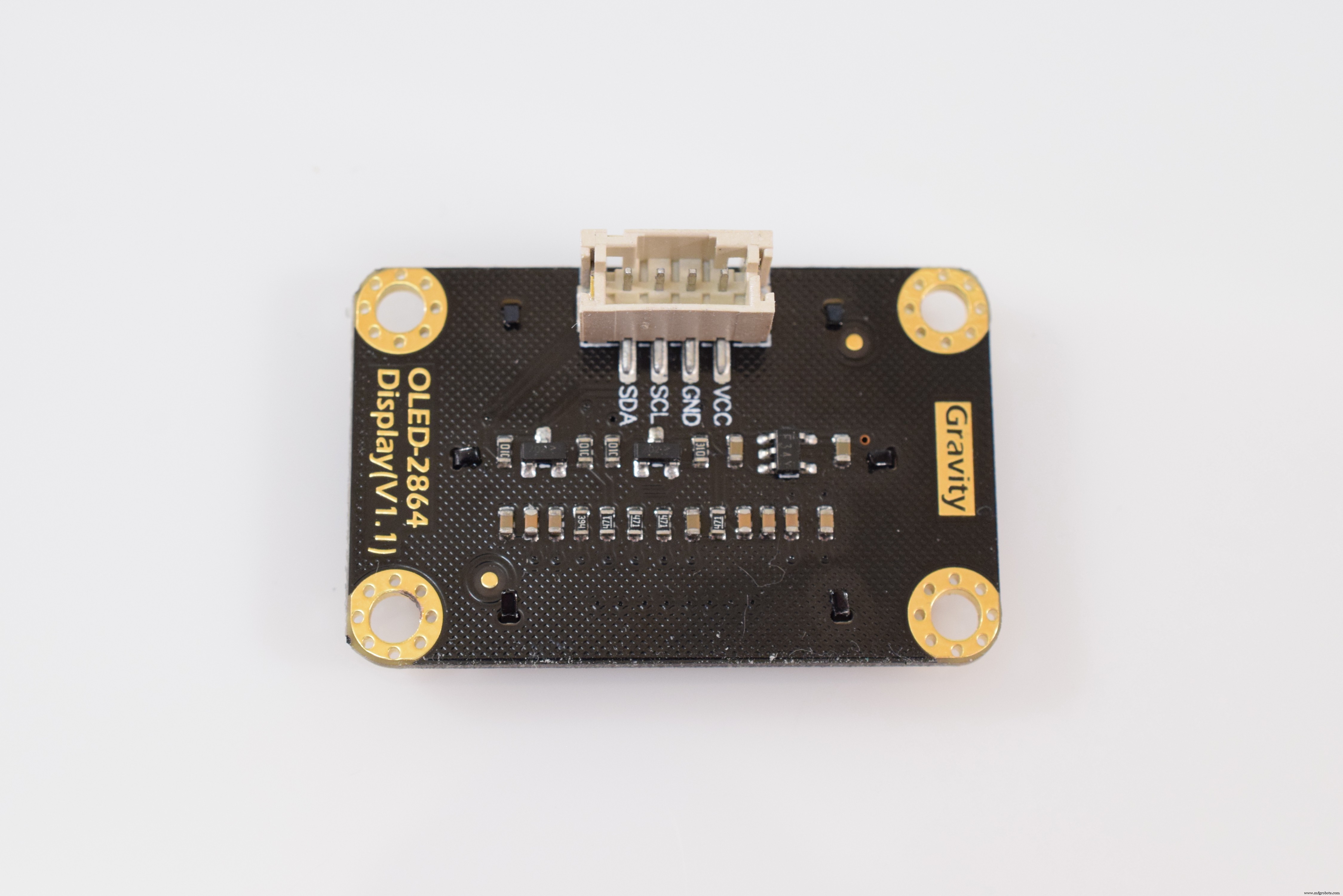
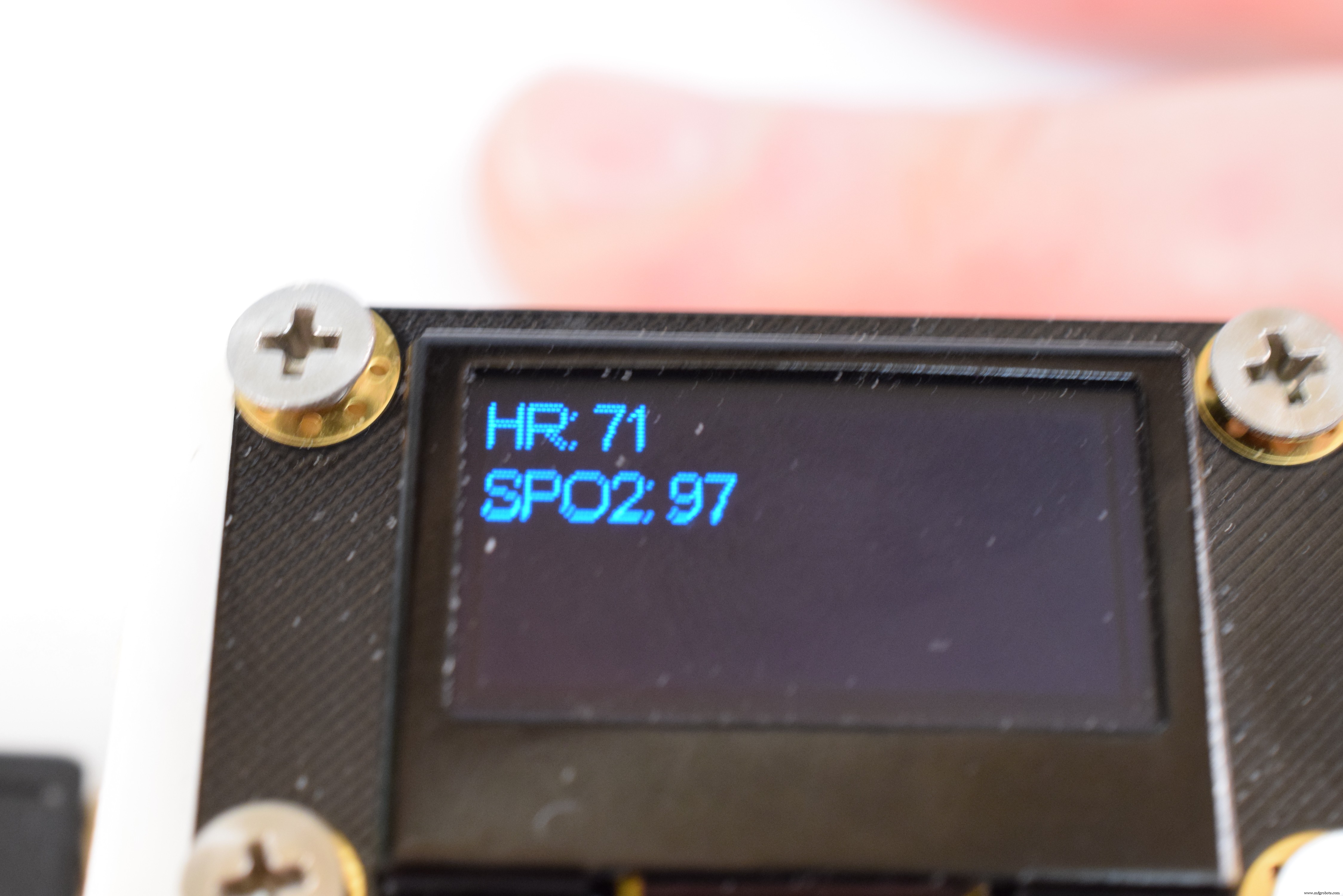
128x64 Pixel OLED
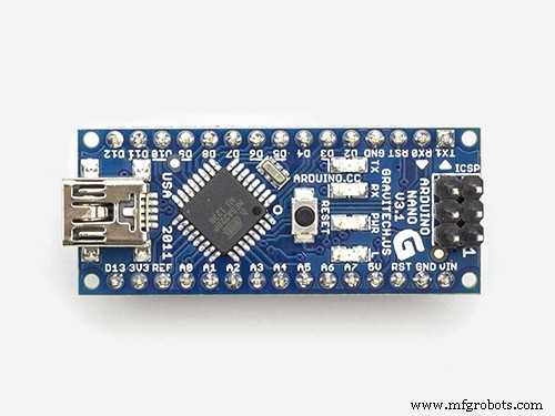
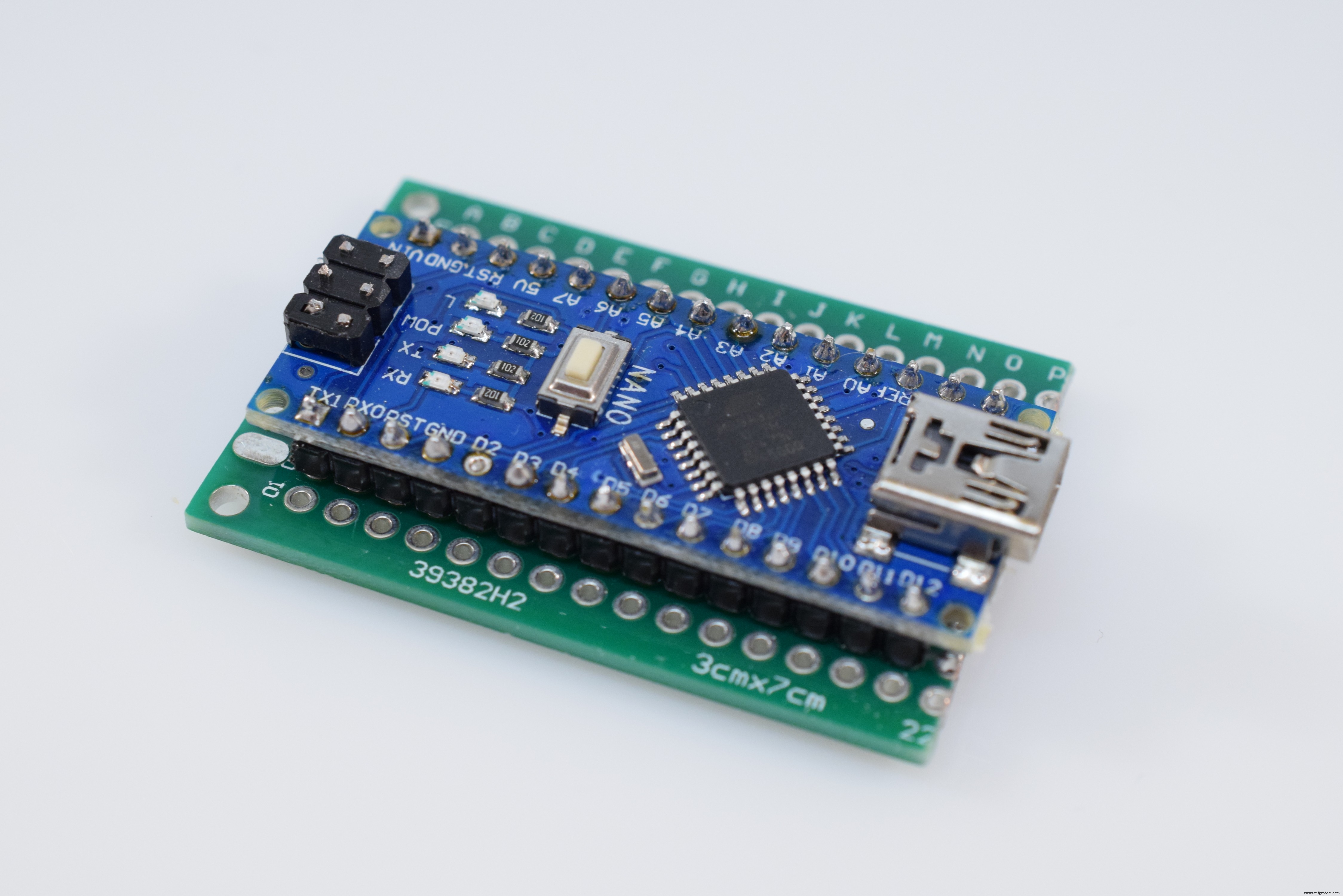
Arduino Nano
Here is a step-by-step walkthrough of how to build this project.
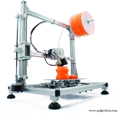
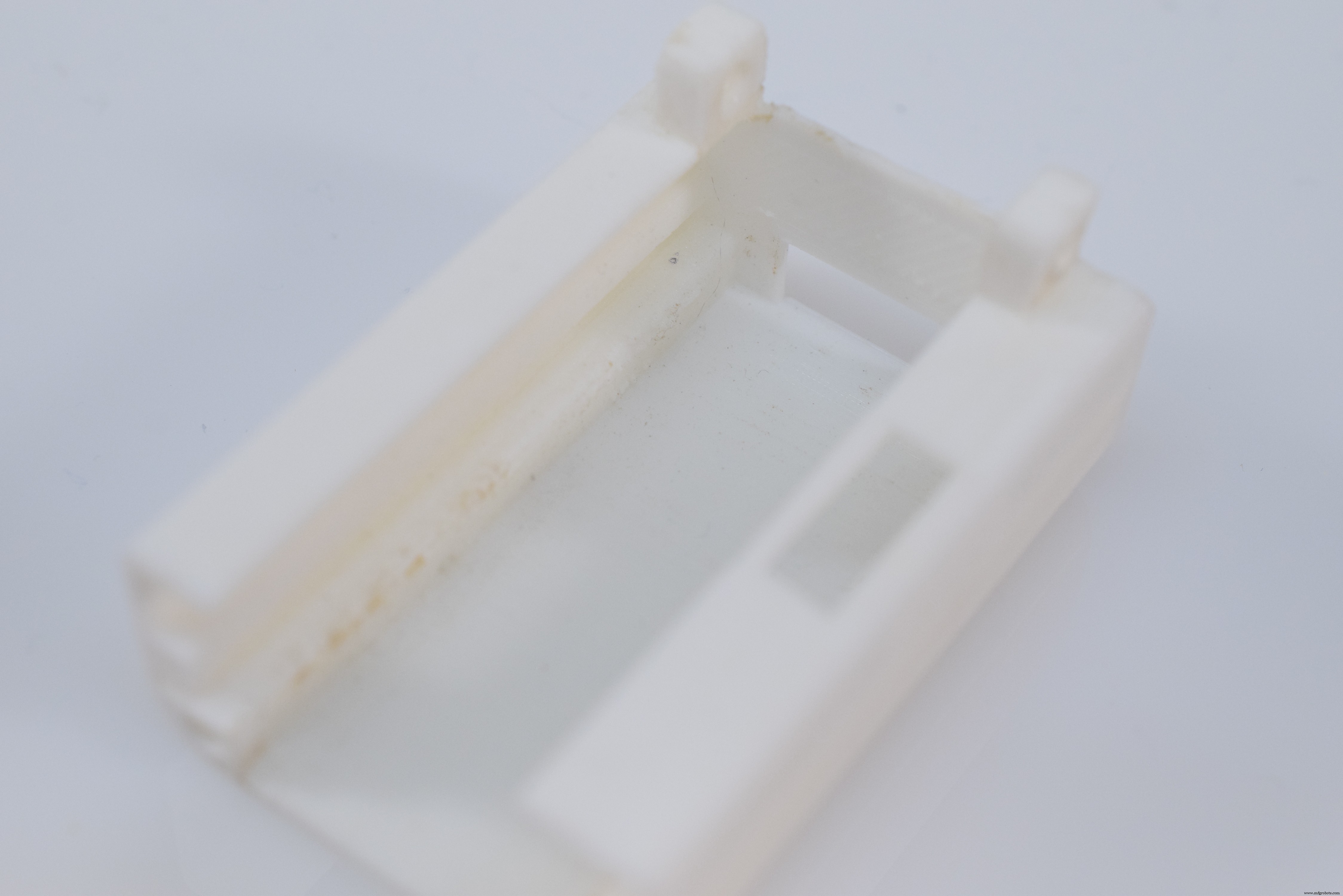
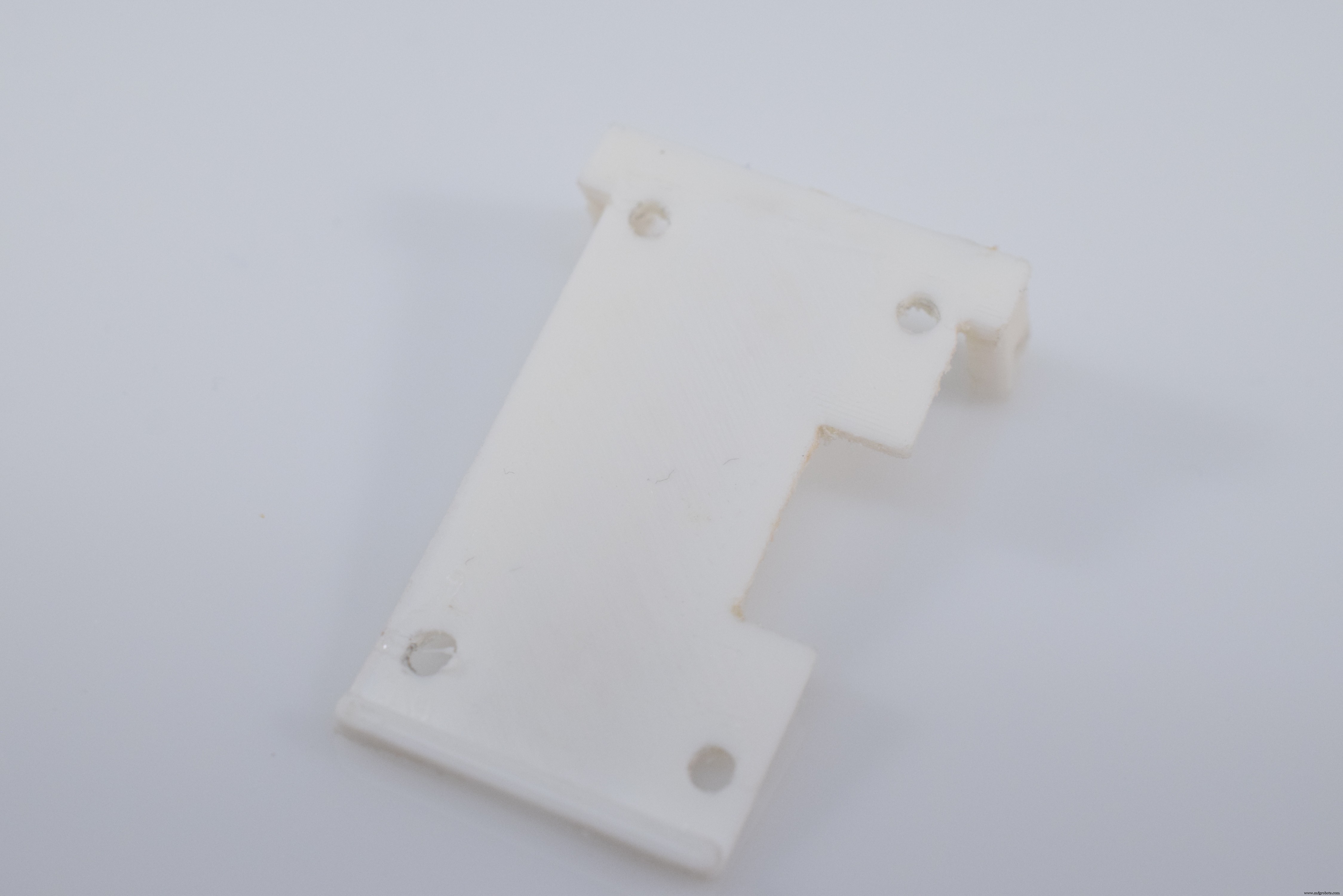
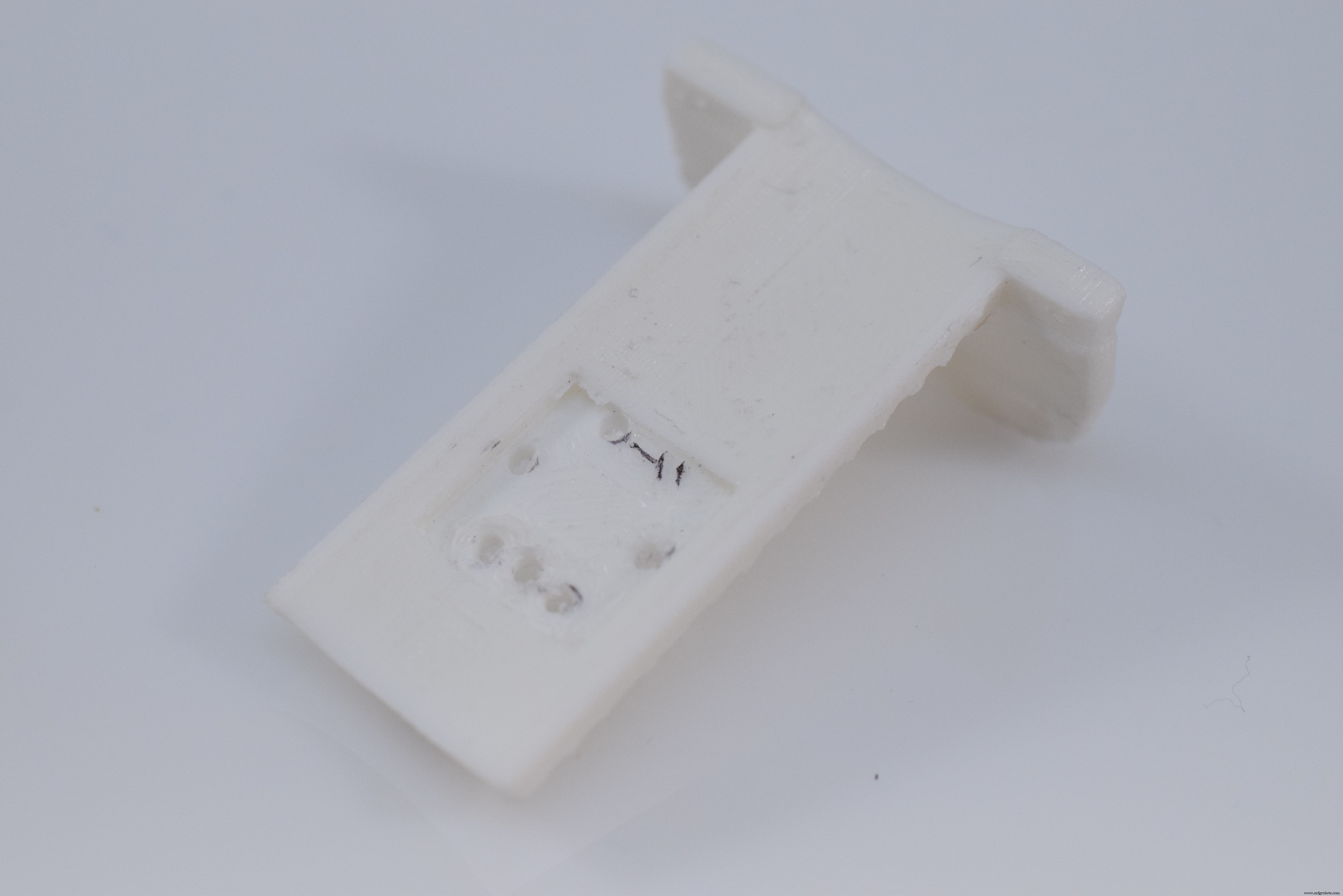
1. Print Out and Clean PartsBegin by downloading each piece from the attachment section on this project and loading it into your slicer of choice. I used an infill of around 70-80% and medium supports, all with PLA. After they were done printing, I removed the supports and did some light sanding to ensure they all fit together nicely.
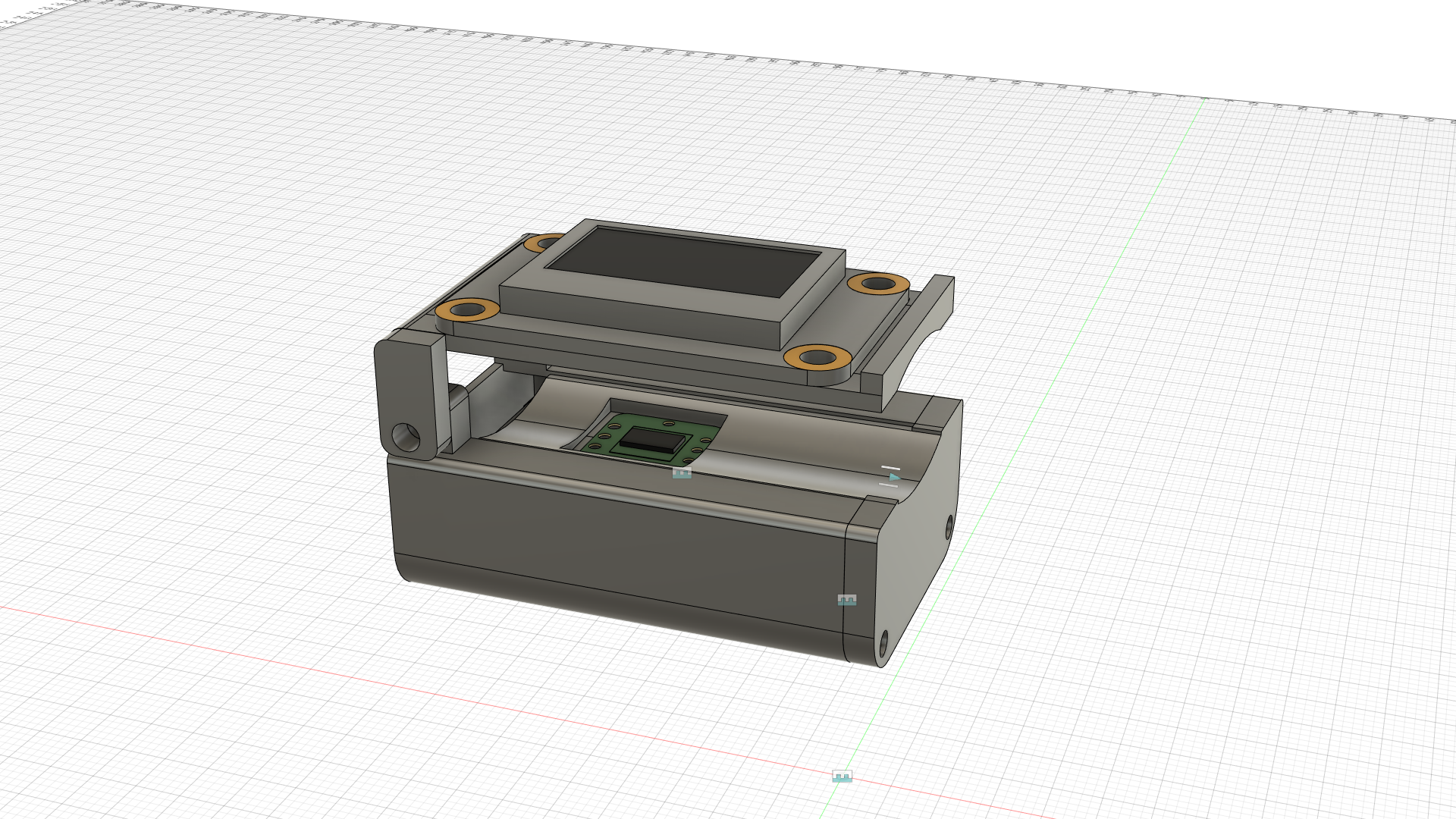
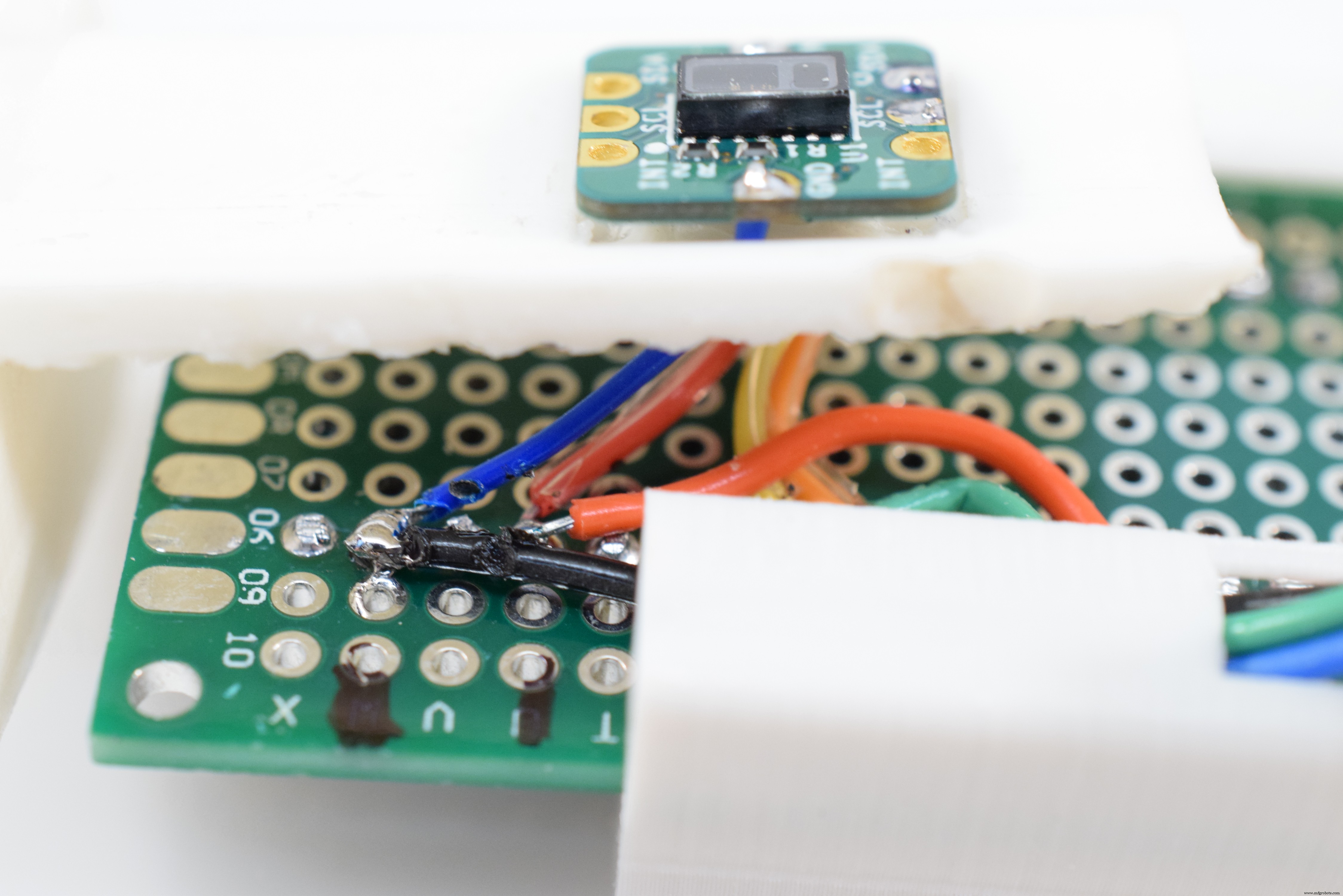
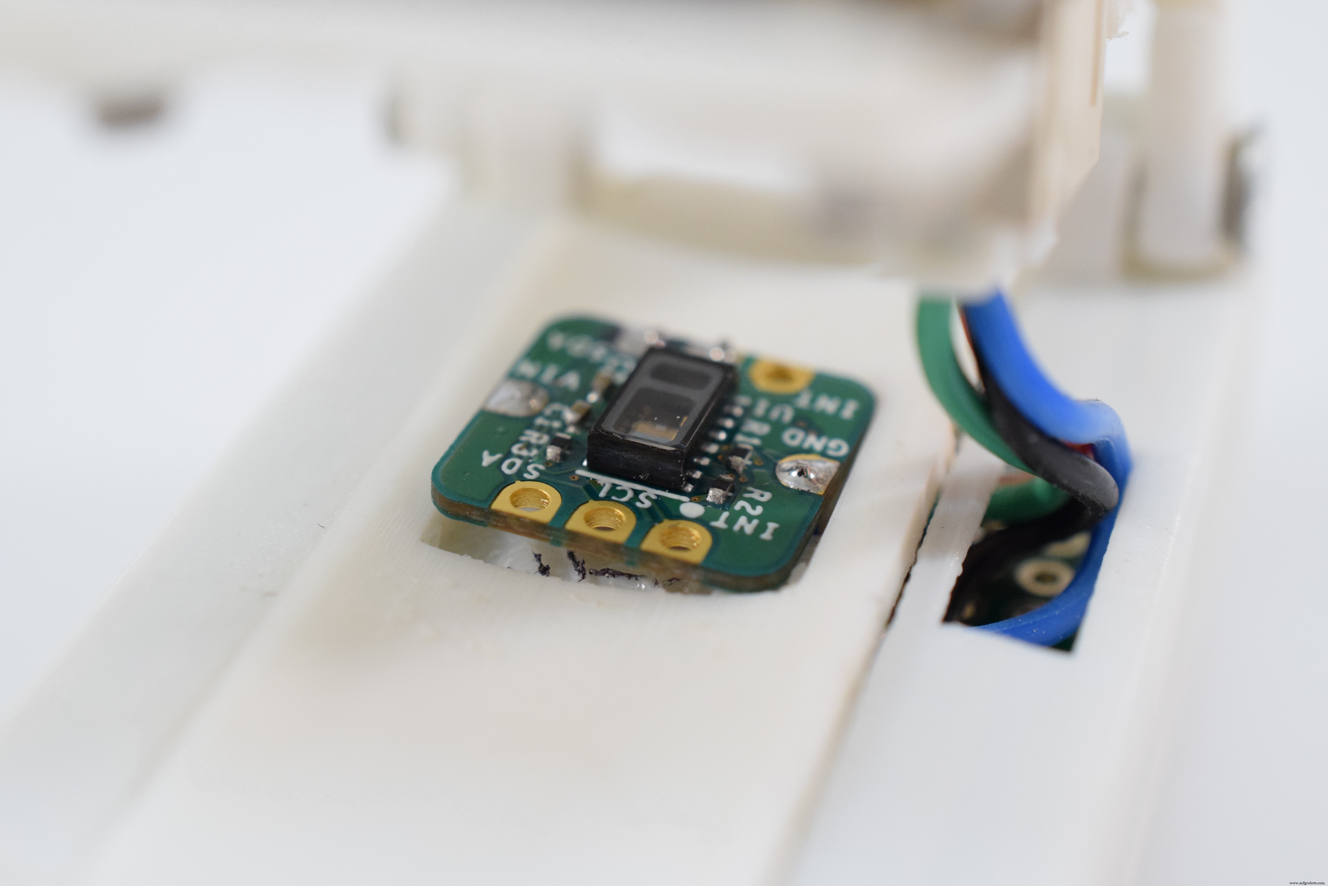
The entire device is designed around an Arduino Nano that is mounted on a piece of 44mm by 30mm perfboard. First, wires get soldered to the VIN, GND, SDA, and SCL pins of the sensor and then run underneath the bed piece to the Arduino Nano.

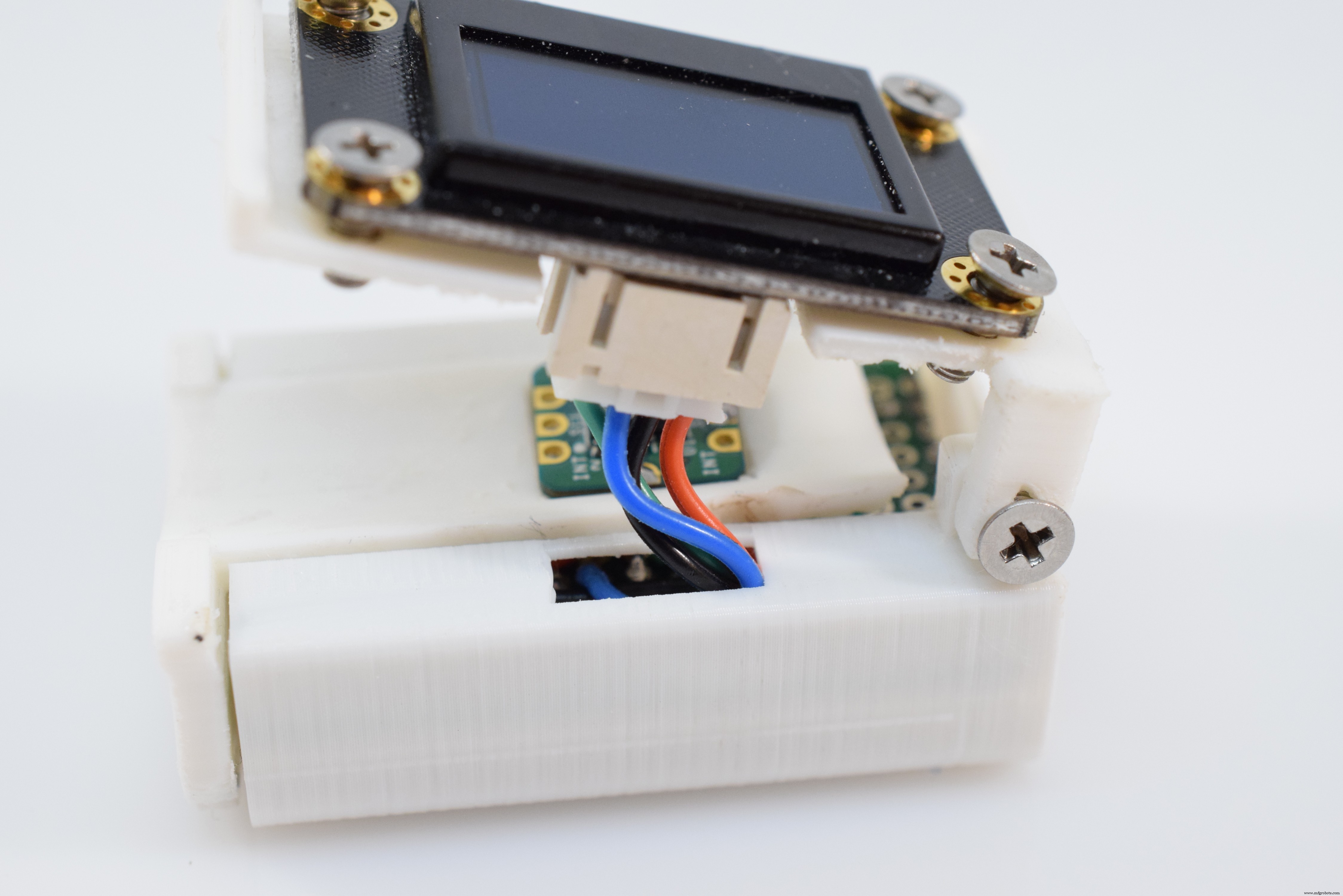
Next, the connector for the OLED is attached to the Nano and then run up to the display itself.
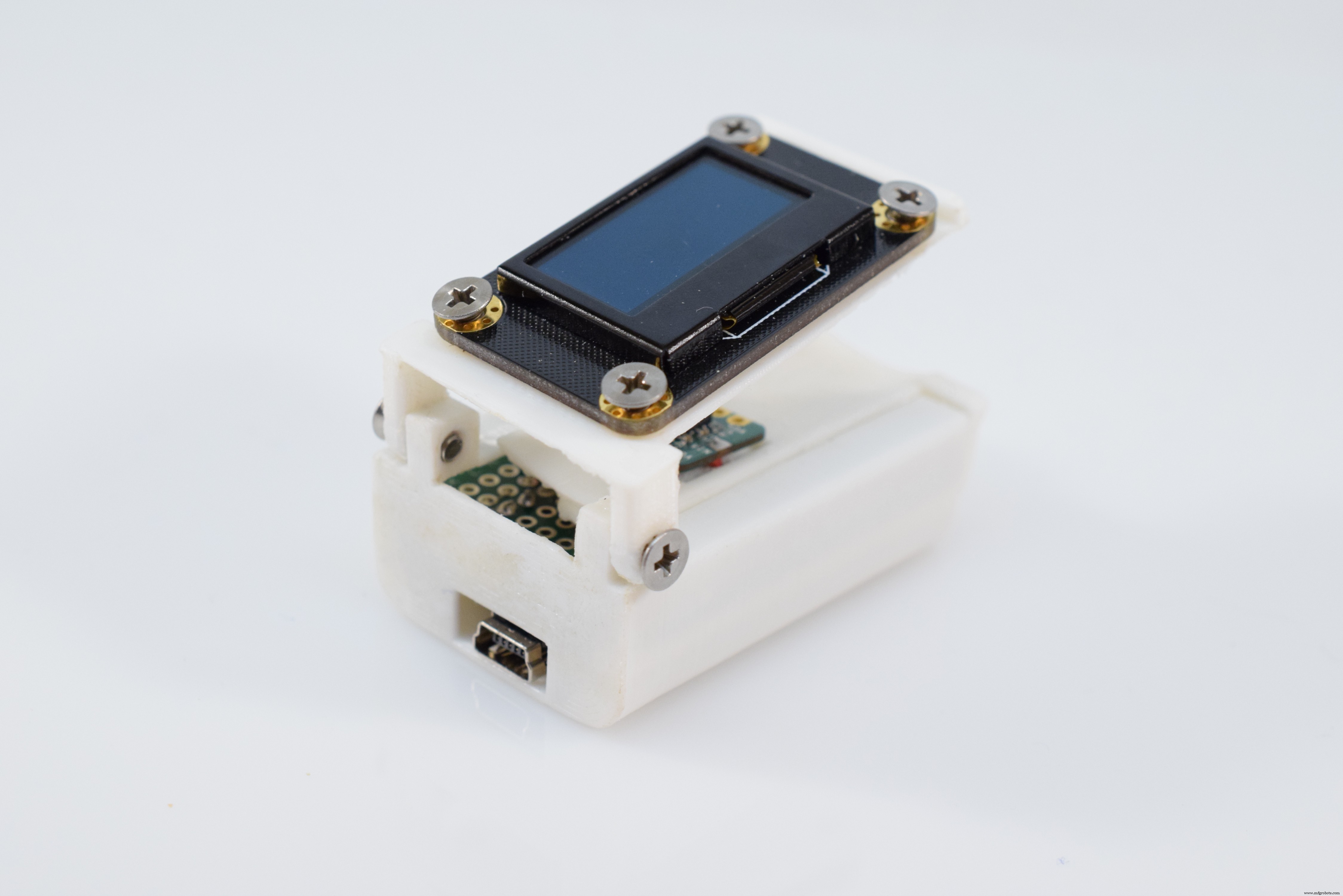
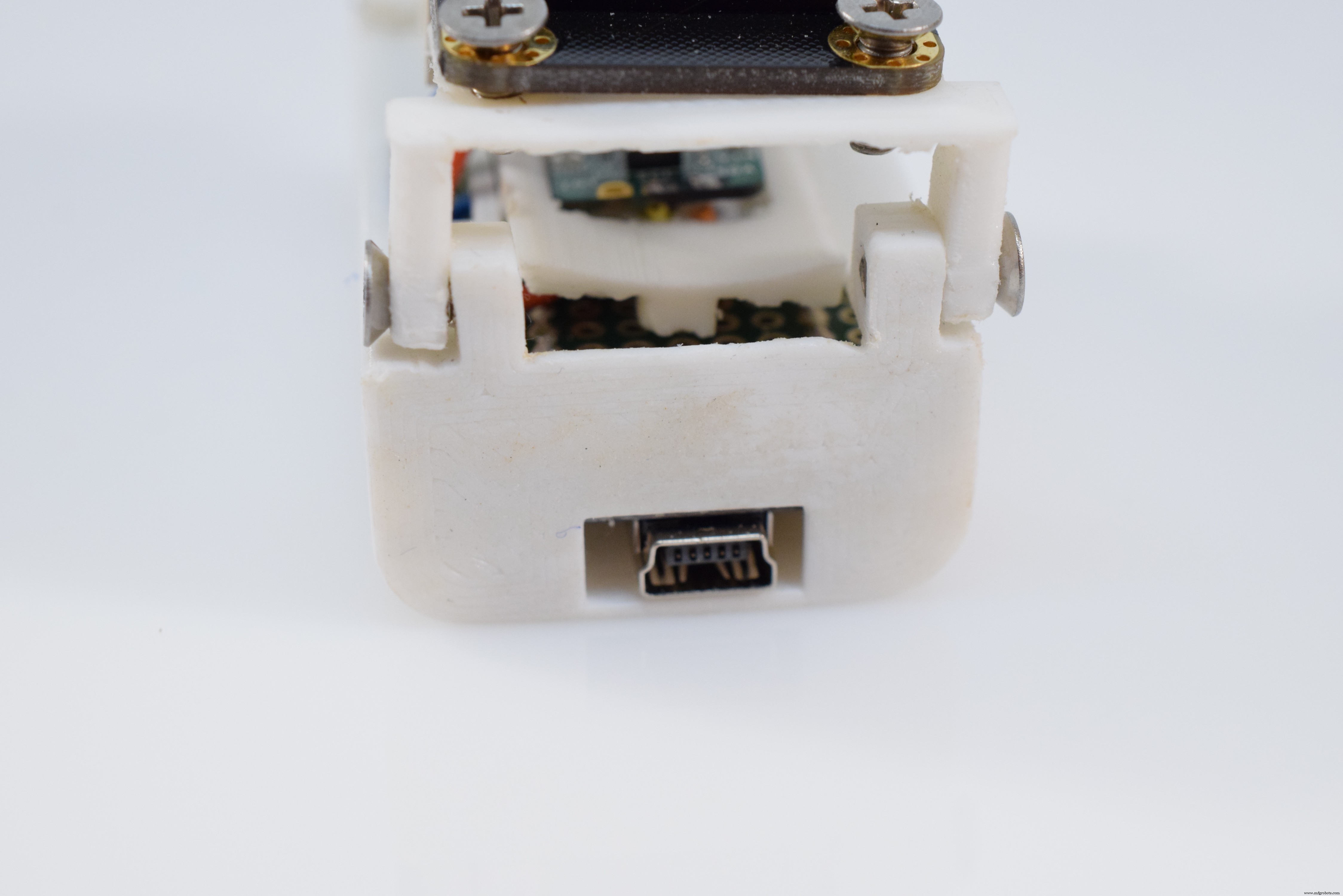
And finally, the entire electronics assembly is slid into the housing and secured with a couple of 3mm screws.
3. Assemble the DeviceAfter the electronics have been inserted, simply attach the OLED screen to the top piece and secure it to the rest of the chassis with a couple of 3mm screws. You can test its motion by gently articulating the lid up and down.
The included sketch performs a couple of actions to display the user's current heartrate and oxygen saturation. To upload it, simply install the required libraries and select Arduino Nano from the board list in the Tools menu and click Upload.
As for the sketch itself, it first initializes the OLED and MAX30102, whilst reporting any errors that might arise. Next, it reads in 100 values to calibrate the sensor and begins displaying them. The device then enters a loop where it reads in 25 new values and computes a moving average with them. Finally, it checks if the values are valid and prints them to the screen if they are.
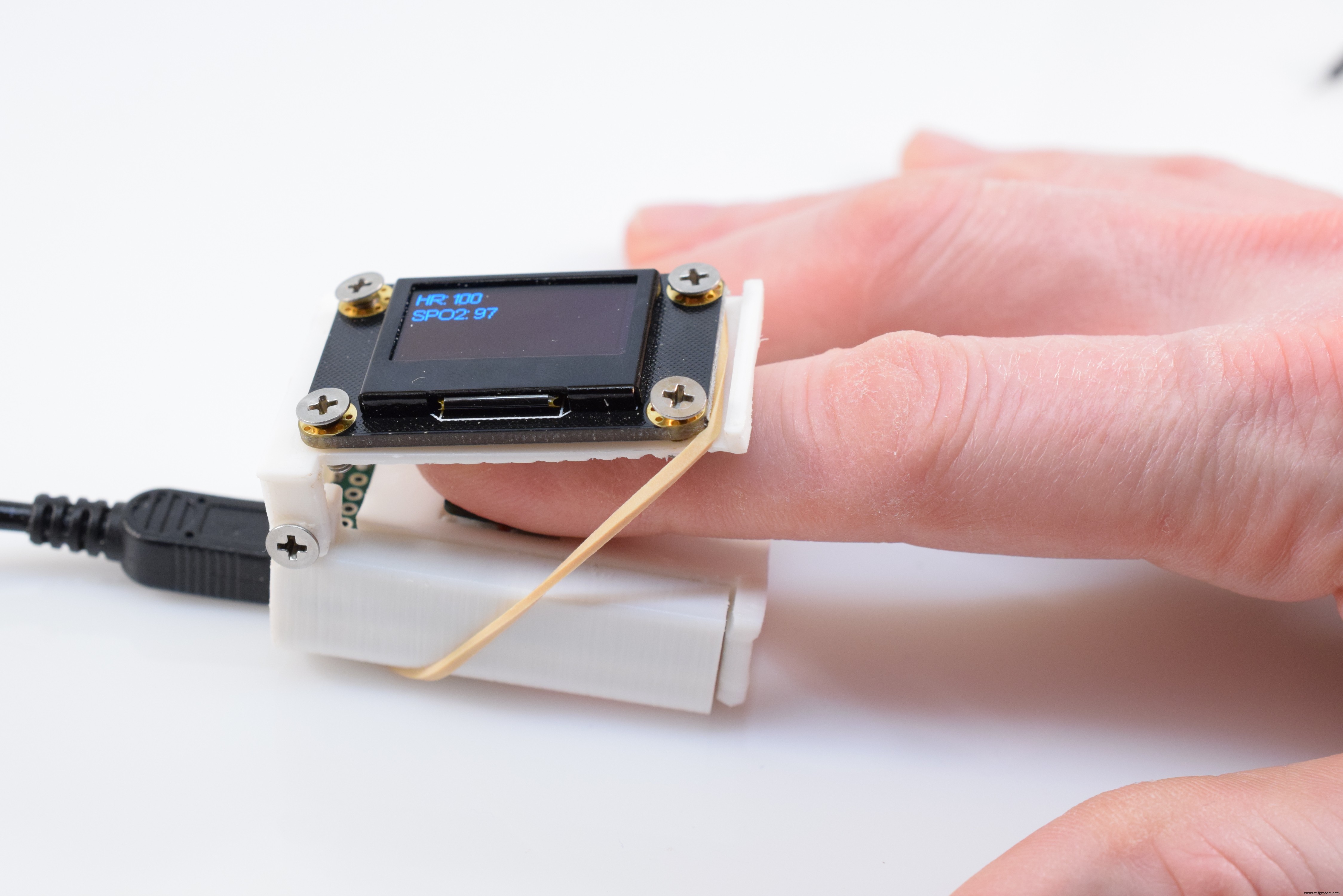
5. Using ItTo use the pulse oximeter, place your fingertip over the sensor and gently close the top lid. Then plug in a power source and simply wait until you see data being displayed.
Code
- Pulse Oximeter Code
Pulse Oximeter CodeC/C++
/*
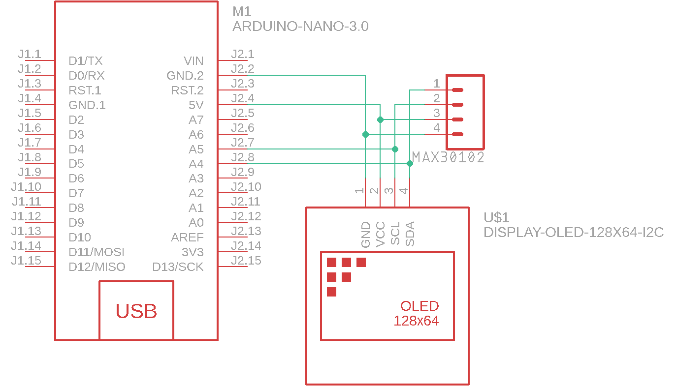
Hardware Connections (Breakoutboard to Arduino):
-5V = 5V (3.3V is allowed)
-GND = GND
-SDA = A4 (or SDA)
-SCL = A5 (or SCL)
-INT = Not connected
The MAX30105 Breakout can handle 5V or 3.3V I2C logic. We recommend powering the board with 5V
but it will also run at 3.3V.
*/
#include <Wire.h>
#include "MAX30105.h"
#include "spo2_algorithm.h"
#include "SSD1306Ascii.h"
#include "SSD1306AsciiWire.h"
MAX30105 particleSensor;
SSD1306AsciiWire oled;
#define MAX_BRIGHTNESS 255
#if defined(__AVR_ATmega328P__) || defined(__AVR_ATmega168__)
//Arduino Uno doesn't have enough SRAM to store 50 samples of IR led data and red led data in 32-bit format
//To solve this problem, 16-bit MSB of the sampled data will be truncated. Samples become 16-bit data.
uint16_t irBuffer[50]; //infrared LED sensor data
uint16_t redBuffer[50]; //red LED sensor data
#else
uint32_t irBuffer[50]; //infrared LED sensor data
uint32_t redBuffer[50]; //red LED sensor data
#endif
int32_t spo2; //SPO2 value
int8_t validSPO2; //indicator to show if the SPO2 calculation is valid
int32_t heartRate; //heart rate value
int8_t validHeartRate; //indicator to show if the heart rate calculation is valid
void setup()
{
Serial.begin(115200); // initialize serial communication at 115200 bits per second:
oled.begin(&Adafruit128x64, 0x3C);
oled.setFont(Arial14);
// Initialize sensor
if (!particleSensor.begin(Wire, I2C_SPEED_FAST)) //Use default I2C port, 400kHz speed
{
Serial.println(F("MAX30105 was not found. Please check wiring/power."));
while (1);
}
particleSensor.setup(55, 4, 2, 200, 411, 4096); //Configure sensor with these settings
}
void loop()
{
//read the first 50 samples, and determine the signal range
for (byte i = 0 ; i < 50 ; i++)
{
while (particleSensor.available() == false) //do we have new data?
particleSensor.check(); //Check the sensor for new data
redBuffer[i] = particleSensor.getRed();
irBuffer[i] = particleSensor.getIR();
particleSensor.nextSample(); //We're finished with this sample so move to next sample
Serial.print(F("red="));
Serial.print(redBuffer[i], DEC);
Serial.print(F(", ir="));
Serial.println(irBuffer[i], DEC);
}
//calculate heart rate and SpO2 after first 50 samples (first 4 seconds of samples)
maxim_heart_rate_and_oxygen_saturation(irBuffer, 50, redBuffer, &spo2, &validSPO2, &heartRate, &validHeartRate);
//Continuously taking samples from MAX30102. Heart rate and SpO2 are calculated every 1 second
while (1)
{
//dumping the first 25 sets of samples in the memory and shift the last 25 sets of samples to the top
for (byte i = 25; i < 50; i++)
{
redBuffer[i - 25] = redBuffer[i];
irBuffer[i - 25] = irBuffer[i];
}
//take 25 sets of samples before calculating the heart rate.
for (byte i = 25; i < 50; i++)
{
while (particleSensor.available() == false) //do we have new data?
particleSensor.check(); //Check the sensor for new data
redBuffer[i] = particleSensor.getRed();
irBuffer[i] = particleSensor.getIR();
particleSensor.nextSample(); //We're finished with this sample so move to next sample
Serial.print(F("red="));
Serial.print(redBuffer[i], DEC);
Serial.print(F(", ir="));
Serial.print(irBuffer[i], DEC);
Serial.print(F(", HR="));
Serial.print(heartRate, DEC);
Serial.print(F(", HRvalid="));
Serial.print(validHeartRate, DEC);
Serial.print(F(", SPO2="));
Serial.print(spo2, DEC);
Serial.print(F(", SPO2Valid="));
Serial.println(validSPO2, DEC);
}
//After gathering 25 new samples recalculate HR and SP02
maxim_heart_rate_and_oxygen_saturation(irBuffer, 50, redBuffer, &spo2, &validSPO2, &heartRate, &validHeartRate);
printToScreen();
}
}
void printToScreen() {
oled.clear();
oled.setCursor(0,0);
if(validSPO2 && validHeartRate) {
oled.print(F("HR: ")); oled.println(heartRate, DEC);
oled.print(F("SPO2: ")); oled.println(spo2, DEC);
} else {
oled.print(F("Not valid"));
}
}
Custom parts and enclosures
Schematics
Manufacturing process
- FirePick Delta Project Log: Building an Open‑Source MicroFactory with OpenPnP
- Build an Arduino Iron Man: Components, Sensors, and Step‑by‑Step Guide
- Find Me: Smart Item Locator with Arduino and Bluetooth
- Portable Pulse Oximeter for Emergency Use During COVID-19
- Build a Custom Arduino Joystick Steering Wheel for Gaming
- PhoneLocator: Securely Locate Your Phone Anywhere
- Health Band: Reliable Smart Wearable Assistant for Seniors
- Ultrasonic Smart Glasses: Enhancing Mobility for the Visually Impaired
- Why Open Source Drives Innovation at the Edge – Essential eBook
- Arduino Breadboard: The Open-Source Solution for Efficient Prototyping