


Step‑by‑Step Guide: Wiring Smart Wi‑Fi Switches in 120/240 V Panels
Wiring Smart Wi‑Fi Switches With or Without Neutral in 120/240 V Panels
Modern smart‑home solutions simplify daily life by turning ordinary lighting circuits into responsive, voice‑controlled environments. By replacing traditional mechanical switches with Wi‑Fi‑enabled devices, homeowners can schedule lights, monitor energy usage, and integrate seamlessly with Alexa, Google Assistant, Apple HomeKit, and Matter. This guide provides clear, NEC‑compliant wiring instructions for Leviton and Legrand smart switches, whether your panel offers a neutral or not.
What Is a Smart Switch?
A smart switch replaces a standard toggle while adding network connectivity. These devices—available from Leviton, Legrand, and other manufacturers—link to your home Wi‑Fi, enabling remote control via mobile apps, voice assistants, and automation platforms. They support scheduling, scene creation, device grouping, and multi‑location operation, making them ideal for bedrooms, kitchens, hallways, and outdoor circuits.
Smart switches offer tangible benefits: energy savings, enhanced security, and hands‑free convenience. In advanced Matter‑enabled systems, they form mesh networks that maintain low‑latency communication across large homes.
Good to Know:
- Smart switches differ from conventional switches; single‑ and multi‑way wiring requires distinct approaches.
- Models such as DN15S (single‑pole, no neutral) and D315S/D215S (three‑way, neutral required) cover most residential scenarios.
- ON/OFF and scheduling are managed via Legrand Home + Control or the My Leviton app.
Key Specifications
- Model: Smart Wi‑Fi Switch
- Pole: Single‑Pole, 3‑Way & Multi‑Way (with or without neutral)
- Voltage: 120 V, 60 Hz, single‑phase AC
- Current: 15 A general, 5 A for LED/CFL/electronic ballast loads
- Load: 1500–1800 W incandescent/halogen or ¾–½ HP motor
- Wire: #14–#12 AWG copper
- Wireless: 2.4 GHz (802.11b/g/n), Bluetooth 5.0
- Range: 30–50 ft (≈9–15 m)
- Compatibility: Alexa, Google Assistant, HomeKit, SmartThings, Matter, IFTTT, Sonos, Schlage Encode™
Wiring a Smart Switch in a Smart Load Center (Neutral Required)
For a 15 A, 120 V smart Wi‑Fi switch controlled by a smart breaker, connect as follows:
- Hot (black) from breaker → LINE
- Neutral (white) → N
- Ground (bare/green) → G
- Load (black from fixture) → LOAD
- Traveler (T) remains unused for single‑load setups.
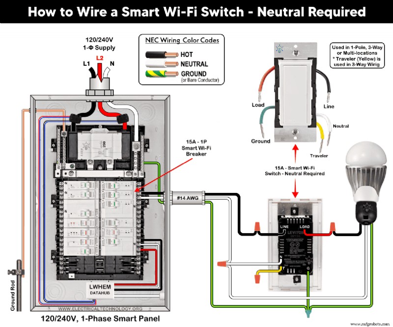
Good to Know: The same wiring applies to Leviton models D315S, D215S, DN15S, ZW15S, D26HD, D2SCS, etc.
Wiring a Smart Switch in a Conventional Panel (No Neutral)
Follow the same diagram, omitting the neutral connection. This method suits retrofit jobs where a neutral is absent. Use an Anywhere Switch Companion and MLWSB Wi‑Fi Bridge for remote control.
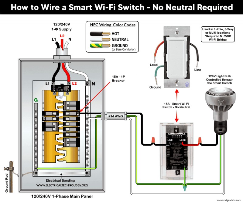
Good to Know: Ideal for older homes lacking a neutral busbar.
Multi‑Location Switching with a Smart Switch Companion
Combine a 15 A smart switch (D315S/D215S) with a DD0SR companion to create two‑way control:
- Neutral and load terminals of both devices connect to the panel’s neutral bus.
- LINE of smart switch → hot from breaker; companion’s BK terminal stays unused.
- Grounds of both devices tie to the panel’s ground bus.
- Traveler (T) on the first switch → YL/RD on the companion.
- LOAD on the smart switch drives the fixture.
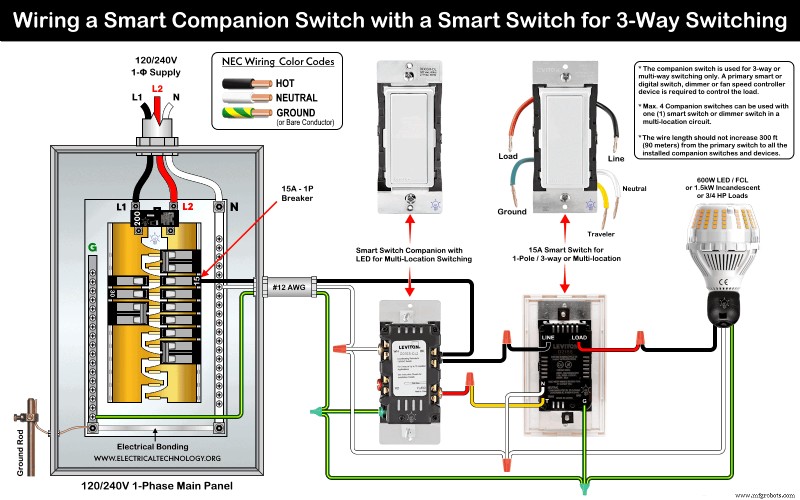
Good to Know:
- When paired with a digital dimmer (DDL06), neutral conductors are tied together and left unused.
- With neutral available, BK and RD terminals remain unconnected in the companion.
Multi‑Way Dimming with a Smart Dimmer Companion
Use a smart switch (D315S/D215S) with a DD00RL dimmer for two‑way dimming:
- LINE and BK of both devices connect to breaker hot.
- Neutral and load terminals of both devices tie to the panel’s neutral bus.
- Grounds of both devices tie to the panel’s ground bus.
- Traveler (T) on the first switch → YL/RD on the dimmer.
- LOAD on the smart switch powers the fixture.
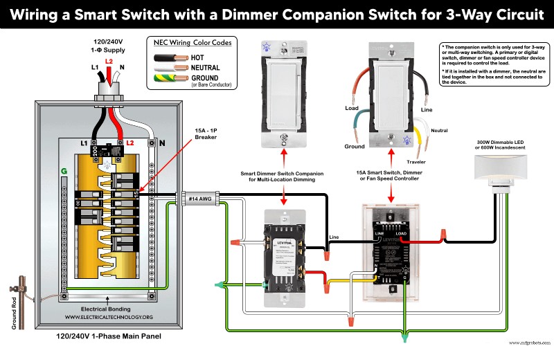
Good to Know:
- Works with Anywhere Switch Companion and MLWSB Wi‑Fi Bridge for wire‑free operation.
- Decora smart switches are incompatible with standard 3‑way/4‑way switches.
Three‑Way Switching with an Ordinary Switch
When a companion device is not preferred, pair a smart switch with a conventional 3‑way rocker:
- Hot from breaker → smart switch black screw.
- Neutral and load → N terminals and silver screws on both devices.
- Ground → G terminals and green screws on both devices.
- Travelers from smart switch (red and yellow/black) connect to brass screws on the 3‑way rocker.
- Load hot from rocker black screw → fixture.
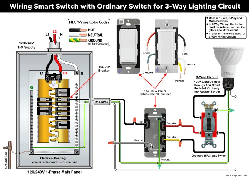
Good to Know:
- Supports 1‑pole, 3‑way, and multi‑location control.
- Travelers are essential only for 3‑way circuits.
- Smart switch must be installed on the line (hot) side.
Adding to Your Network and App
Press the top rocker for 7 s until the amber light appears, then release. A green flash indicates the device is ready to join your Wi‑Fi network.
Install the My Leviton app (for Leviton devices) or Home + Control (for Legrand). Both are available on Google Play and the Apple App Store.
In the app, tap “+” → “Add a device” and follow the on‑screen steps. Once configured, you can control lighting from anywhere.
Troubleshooting via LED Status
Below is a quick reference for Leviton and Legrand smart switches. Refer to the manufacturer’s guide for detailed diagnostics.
Leviton LED Indicators
| Color | Status | Indication |
|---|---|---|
| Green (flashing) | Setup mode | Add to Wi‑Fi |
| Green (slow blink) | Connecting | Wi‑Fi |
| Green/Off (solid) | Normal | Operation |
| Amber (slow blink) | Not connected | Wi‑Fi |
| Green/Amber (alternating) | Wireless mode | Device |
| Red (blinking) | Unpaired | Wireless |
| Green/Red/Amber (alternating) | Feature triggered | App |
Legrand LED Indicators
| Color | Status | Indication |
|---|---|---|
| Green (blinking) | Setup | Add to Wi‑Fi |
| Green (solid) | Online | Network |
| White (solid) | Connected but off | Device |
| Green/Red (blinking) | Resetting | Factory default |
| Red (solid) | Not in network | Factory reset |
Installation Precautions
- Disconnect power at the main breaker before working.
- Per NEC 310.16, 210.24(1), and 240.4(D)(4), use #14 AWG copper for a 15 A, 120 V circuit.
- Strip non‑factory‑stripped conductors: 3/4" for side wiring, 1/2" for back wiring.
- Tighten terminal screws to 14–18 in·lb (1.6–2.0 N·m) or as specified by the manufacturer.
- Keep the wire run between the switch and companion under 300 ft (90 m).
- Install 15 A devices on a 15 A breaker only.
- Use devices only indoors.
- If unsure, consult a licensed electrician and local codes.
Disclaimer: The author assumes no responsibility for injury or damage resulting from improper installation. Electrical work is hazardous; exercise caution.
Further Learning Resources
Smart Device Wiring Series
- How to Wire 120/240 V Smart Load Center with Smart Breakers
- How to Wire a Smart Breaker in a Smart 120/240 V Panel
- How to Wire a Smart GFCI Breaker in a 120/240 V Smart Panel
- How to Wire Smart AFCI/GFCI Breaker in a Smart Load Center
- How to Wire a 15 A Wi‑Fi Smart Outlet in a Smart Panel
- How to Wire 15 A and 20 A Wi‑Fi Smart GFCI Outlets
Main Panels Wiring Tutorials
- How to Wire 120/240 V Main Panel – Breaker Box Installation
- How to Wire 120/208 V, 1‑Phase & 3‑Phase Main Panel?
- How to Wire 120/208/240 V High Leg Delta 1‑Phase & 3‑Phase Main Panel?
- How to Wire 277/480 V, 1‑Phase & 3‑Phase Main Service Panel?
- How to Wire 347/600 V, 1 and 3‑Phase Main Service Panel?
- How to Wire a Subpanel? Main Lug Installation for 120 V/240 V
- How to Wire a Spa Panel Box for a Hot Tub using 2P GFCI & Breaker
- Single Phase Electrical Wiring Installation in Home – NEC & IEC
- Three Phase Electrical Wiring Installation in Home – NEC & IEC
- How To Wire a Single Phase kWh Meter – 120 V/240 V
- How to Wire a Three‑Phase Meter? 120/208/240/277/347/480/600 V
Wiring Smart / Standard GFCI & Breakers
- How to Wire a 1‑Pole Breaker
- How to Wire a 2‑Pole Breaker
- How to Wire a 3‑Pole Breaker
- How to Wire a 1‑Pole GFCI
- How to Wire a 2‑Pole GFCI
- How to Wire a 3‑Phase, 3‑Pole GFCI
- How to Wire a Tandem Breaker
- How to Wire GFCI Circuit Breakers
- How to Wire an AFCI Breaker
Wiring Smart / General Outlets & GFCI/AFCI Receptacles
- How to Wire an Outlet Receptacle? Socket Outlet Wiring Diagrams
- How to Wire a GFCI Outlet?
- How to Wire a 3‑Way Combination Switch and Grounded Outlet?
- How to Wire a 15 A – 125 V Outlet – NEMA 5‑15 Receptacle
- How to Wire a 20 A – 125 V Outlet – NEMA 5‑20 Receptacle
- How to Wire a 15 A – 250 V Outlet – NEMA 6‑15 Receptacle
- How to Wire a 20 A – 250 V Outlet – NEMA 6‑20 Receptacle
- How to Wire a 50 A – 125/250 V Outlet – NEMA 14‑50 Receptacle
Switches Wiring
- How to Wire Single Pole, Single Throw (SPST) as 2‑Way Switch?
- How to Wire Single Pole, Double Throw (SPDT) as 3‑Way Switch?
- How to Wire Double Pole, Single Throw Switch? Wiring DPST
- How to Wire Double Pole, Double Throw Switch? Wiring DPDT
- How to Wire Double Switch? 2‑Gang, 1‑Way Switch – IEC & NEC
- How to Wire 4‑Way Switch (NEC) or Intermediate Switch as 3‑Way (IEC)?
- How to Wire Auto & Manual Changeover & Transfer Switch – (1 & 3 Phase)
Sizing Breakers, Wires, and Panels
- How to Size a Load Center, Panelboards and Distribution Board?
- How to Determine the Right Size Capacity of a Subpanel?
- How to Find the Proper Wire Size for 100A Service 120 V/240 V Panel?
- How to Size a Circuit Breaker?
- How to Find the Proper Size of Wire & Cable in Metric & Imperial Systems
- How to Size a Breaker and Wires in AWG with EGC for Load?
- How to Size Service‑Entrance Conductors and Feeder Cables?
- How to Size Feeder Conductors with Overcurrent Protection?
- How to Size a Branch Circuit Conductors with Protection?
- How to Size Equipment Grounding Conductor (EGC)?
- How to Size Grounding Electrode Conductor (GEC)?
- How to Size Main Bonding Jumper (MBJ)?
- How to Size Motors FLC, HP, Voltage, Breaker Size and Wire Size?
- What is the Correct Wire Size for 100A Breaker and Load?
- What is the Right Wire Size for 15A Breaker and Outlet?
- What is the Suitable Wire Size for 20A Breaker and Outlet?
Finding the Number of Breakers/Outlets in a Circuit
- How to Determine the Number of Circuit Breakers in a Panelboard?
- How to Find the Number of Outlets on a Single Circuit Breaker?
- How to Find Voltage & Ampere Rating of Switch, Plug, Outlet & Receptacle
- How to Calculate the Number of Fluorescent Lamps in a Final Sub Circuit?
- How to Calculate the Number of Incandescent Lamps in a Final Sub Circuit?
- How to Determine the Number of Lighting Branch Circuits?
- How to Determine the Number of Branch Circuits? – 3 Ways
- How to Find the Number of Lights on a Single Circuit Breaker?
General Wiring Installation Tutorials
- How to Toggle Electric Water Heater Between 120 V and 240 V?
- How to Wire 120 V Water Heater Thermostat – Non‑Simultaneous?
- How to Wire 240 V Water Heater Thermostat – Non‑Continuous?
- How to Wire 3‑Phase Simultaneous Water Heater Thermostat?
- How to Wire Twin Timer for 120 V/240 V Circuits – ON/OFF Delay
- How to Wire ST01 Timer with Relay & Contactor for 120 V/240 V Motors?
- How to Wire Multifunction ON/OFF Delay Timer for 120 V/240 V Motors?
- Even More Residential Wiring Installation Tutorials
Industrial Technology
- Sheet Metal Laser Cutting: Mastering the Fundamentals of Precision Metal Fabrication
- The Evolution of SPICE: From CANCER Roots to Modern Circuit Simulation
- LM358 Op-Amp User Guide: Features, Pinouts & Applications
- Optimizing Injection Molding with Ejector Pins: Types & Best Practices
- Understanding the Distinct Roles of Shop Drawings vs. Design Drawings in Structural Steel Projects
- IoB Exclusive: Christine Moroz, Sysco Prairie Region VP of Merchandising, Shares Industry Insights
- Harness IoT to Streamline Seasonal Supply Chains and Meet Rapid Delivery Demands
- Analog Solver Outperforms Digital Computers on NP-Hard Optimization
- Enhancement‑Mode IGFETs: Fundamentals, Applications, and Design Considerations
- Streamlining Clinician Workflows with Advanced Supply Chain Management Systems