


Installing 15A & 20A Wi‑Fi Smart GFCI Outlets – A Complete Wiring Guide
How to Wire a Smart GFCI Outlet in 120/240V Panels
Wi‑Fi Smart GFCI outlets combine ground‑fault protection with real‑time mobile alerts. When a fault occurs, the device sends an instant notification to your smartphone via the My Leviton app, giving you peace of mind without sacrificing safety.
These outlets are ideal for high‑risk areas such as garages, basements, and outdoor spaces where routine checks are uncommon. They can also be paired with other Decora Smart devices for a fully integrated home‑monitoring system.
What Is a GFCI and Where Should It Be Installed?
A Ground‑Fault Circuit Interrupter (GFCI) monitors the current balance between hot and neutral. If an imbalance is detected, it instantly disconnects the circuit to prevent electric shock. The NEC 210.8(A) mandates GFCI protection in kitchens, bathrooms, laundry rooms, workshops, basements, garages, carports, and outdoor areas such as pools, decks, and patios.
- GFCI outlets protect both the device plugged into them and any downstream outlets on the same circuit.
- They do not guard against short circuits or overloads.
- Leviton offers 15A (D2GF1) and 20A (D2GF2) models.
- The status LED indicates power, protection, and wiring integrity.
- An optional audible alarm can be toggled via the My Leviton app.
Key Technical Specifications
- Model: Decora Smart Wi‑Fi GFCI Outlet – NEMA 5‑15 / 5‑20
- Poles: 2‑pole, 3‑wire (grounded)
- Voltage: 125 V, 60 Hz, single‑phase
- Current: 15 A or 20 A
- Trip Level: Class A, 5 mA ± 1 mA
- Short‑Circuit Rating: 10 kA
- Wire Size: #14 AWG for 15 A, #12 AWG for 20 A (copper)
- Terminations: Back‑wire or side‑wire compatible
- Compatibility: All Decora devices, My Leviton app
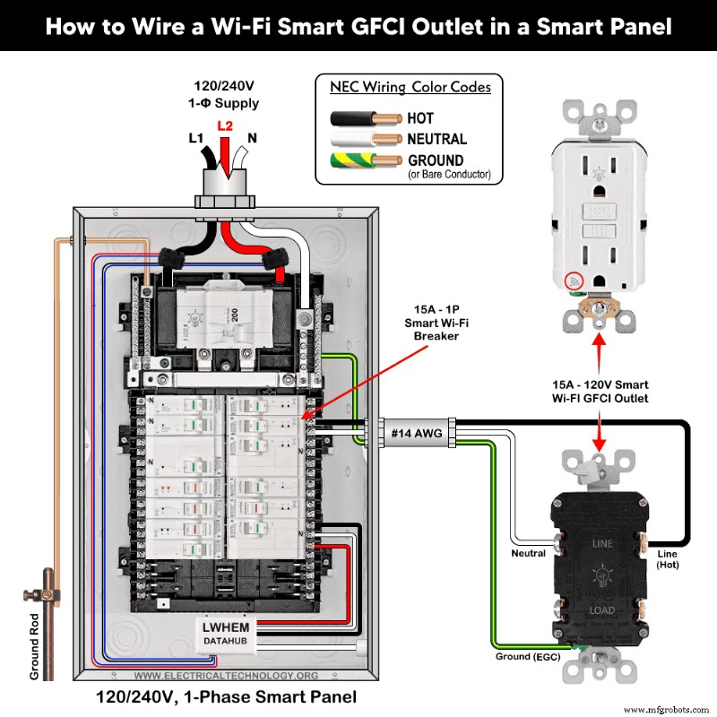
Installing a 15A Smart GFCI in a Smart Panel
- Turn Off Power – Switch off the main breaker before beginning.
- Verify Circuit – Confirm the outlet is on a 15 A, 120 V circuit with a single‑pole breaker and #14 AWG conductors.
- Identify LINE vs. LOAD – LINE feeds power from the panel; LOAD passes power to downstream outlets. If only one cable enters the box, it’s LINE. With two cables, use a non‑contact tester after a brief power pulse to determine the live conductor.
- Strip and Terminate Wires – Strip 19 mm (¾”) of insulation for side‑wire or 16 mm (⅝”) for back‑wire. Connect:
- Black (hot) to brass “LINE” screw
- White (neutral) to silver “LINE” screw
- Green/bare (ground) to green screw
- Mount the Device – Secure the outlet in the box, attach the cover plate.
- Restore Power and Test – Turn on the main breaker and the circuit breaker. Press the RESET button; a solid green LED confirms correct wiring. Press TEST to verify the outlet trips, then press RESET again.
Below is a wiring diagram for a 15 A, 120 V smart GFCI (Decora D2GF1‑KW) supplied by a 15 A single‑pole Wi‑Fi smart breaker in a Leviton smart panel.
LED Status Indicators
- Solid GREEN – powered and functioning
- Flashing/RED – fault or miswire
- OFF – tripped or no load power
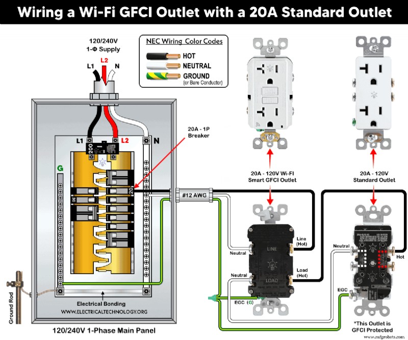
Installing a 20A Smart GFCI with a Standard Outlet
The LINE side wiring is identical to the 15 A installation. For downstream protection, connect the LOAD terminals:
- Remove the yellow sticker covering the LOAD terminals.
- Attach the outgoing hot to the brass “LOAD” screw; then connect to the brass terminal of the standard 20 A outlet.
- Attach the outgoing neutral to the silver “LOAD” screw; then connect to the silver terminal of the standard outlet.
- Join all ground wires and secure them to the green screw.
Below is a diagram illustrating a 20 A, 120 V smart GFCI wired with a conventional 20 A outlet on a 20 A single‑pole breaker using #12 AWG conductors.
Important Note
- Outlets connected to the LOAD terminals are protected by the GFCI.
- Outlets connected to the LINE terminals are not protected.
Smart Features & Safety Controls
- Use the My Leviton app to add the device, enable notifications, and toggle the audible alarm.
- Remote ON/OFF control is disabled by design to maintain code compliance and safety.
Installation Precautions
- Use #14 AWG for 15 A circuits, #12 AWG for 20 A circuits.
- Follow the device’s torque specifications (14–18 in·lb).
- A 15 A outlet must not be used on a 20 A circuit; conversely, a 20 A plug will not fit a 15 A receptacle.
- Only use 15 A receptacles on 15 A breakers; only use 20 A receptacles on 20 A breakers.
Safety Warning
- Always disconnect the main power before working on any circuit.
- If unsure, consult a licensed electrician.
- Improper installation can result in electric shock or fire.
Further Learning Resources
Explore additional wiring tutorials and best practices in our Leviton Learning Center.
Related Smart Wiring Guides
Industrial Technology
- Machining Fundamentals: Mastering Lathe Operations
- Tantalum Capacitor Marking: A Comprehensive Guide to Types and Identification
- Master Resistor Circuit Diagrams: Expert Guide to Series, Parallel, and Hybrid Connections
- Wire Connection Conventions in Electrical Schematics: A Clear Guide
- Choosing the Right CMMS: Free, Open Source, or Trial Software Explained
- How Retailers Can Win Over Hybrid Shoppers
- 5 Essential Network Security Strategies for Small Businesses
- The Critical Role of Unique Identification in Industrial Asset Management
- 3 Key Metrics to Optimize Last‑mile Delivery Labor Performance
- DIY LED Grow Light: The Ultimate Step‑by‑Step Guide for Home Greenhouse Success