


Comprehensive Guide to Injection Molding Gate Types and Design Best Practices
Choosing the right gate is pivotal to achieving high‑quality plastic parts. Each gate design offers distinct advantages for flow, finish, and production efficiency. Below is a detailed overview of the most common gate types, along with practical guidance on placement, sizing, and application.
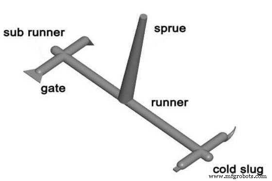
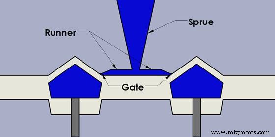
1. Direct or Sprue Gates
Direct (sprue) gates are the simplest and most widely used. The molten plastic travels straight from the sprue into the cavity, allowing rapid filling of large volumes with minimal pressure and short feeding times. They are ideal for non‑aesthetic, deep‑cavity parts such as appliance housings, bins, and printers.
While cost‑effective, these gates leave a visible mark that must be manually trimmed, which can add post‑processing time and surface blemishes.
2. Edge Gates
Edge gates sit along the part’s perimeter, creating a clear, easily removable mark. Their larger cross‑section promotes smooth flow, making them suitable for flat or medium‑thick components where aesthetics are less critical.
They require no special resin, and their straightforward geometry keeps tooling costs down.
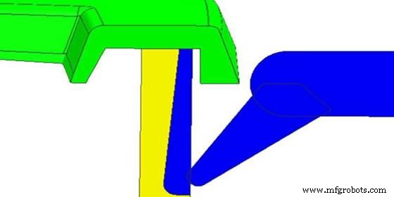
3. Submarine (Tunnel) Gates
Placed below the parting line, submarine gates feed the cavity from beneath, allowing automatic trimming during ejection. The narrow channel limits melt volume, making them best for small, precision parts.
Using them on large parts can lengthen cycle times and produce shear‑related surface defects.
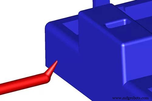
4. Cashew Gates
Shaped like a walnut, cashew gates reach into tight or irregular areas that conventional tunnels cannot access. Their curved geometry requires careful design to avoid distortion during part removal.
Because they are not limited to a specific resin, cashew gates are versatile for complex geometries.
5. Diaphragm Gates
Diaphragm gates taper from beneath the gate, minimizing weld lines on angular parts. They provide even flow for larger components and work well with most resin types.
By controlling temperature, speed, and pressure, diaphragm gates deliver smooth surfaces and reduced defects.
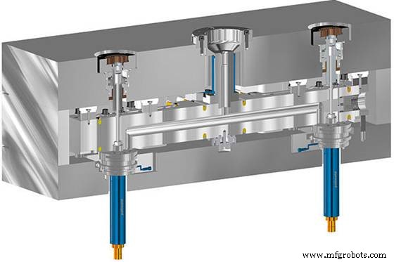
6. Hot‑Runner Valve Gates
In hot‑runner systems, valve gates keep the melt at a constant temperature and pressure. A retractable pin regulates flow: pulling the pin releases melt, pushing it back pushes any excess back into the mold, preventing gate buildup.
This precise control boosts efficiency and allows independent management of multiple gates.
7. Hot‑Runner Thermal Gates
Thermal gates function without a valve, resting just above the parting line. When flow stops, the residual melt forms a “cold slug” that melts into the cavity as the next injection begins, eliminating gate trimming.
They are compatible with a wide range of resins and are especially advantageous for high‑volume, high‑speed production.
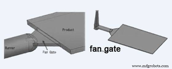
8. Fan Gates
Fan gates feature a broad, widening opening that ensures uniform thickness across large or flat parts. Their design mitigates directional stress and flow marks, making them ideal for polycarbonate and other high‑clarity plastics.
9. Pin Gates
Pin gates are small, often located near ejector pins on the B‑side of the mold. While they reduce gate size, they can increase scrap due to the large runner needed, making them best for specific multi‑plate molds.
When selecting a gate, consider the following critical factors:
Gate Placement
Position the gate in the deepest cross‑section to promote even flow and minimize voids. Avoid placing gates near high‑stress areas that could compromise part integrity.
Gate Size
Choose a gate dimension that balances shear heating and flow pressure. Too small increases shear, while too large can cause excessive pressure spikes.
Part Shape and Finish
Match the gate design to the part geometry and desired surface quality. For example, cashew gates excel with small, intricate parts requiring a smooth finish.
Common Questions
Where should the gate be placed? Install it in the deepest section, on one side of the mold, to ensure optimal flow and reduce stress.
What are the basic steps of injection molding? Clamping → Injection → Cooling → Ejection.
What defects are typical? Sink marks, flow lines, warping, delamination, short shots, and jetting can occur if gate design or process parameters are suboptimal.
Industrial Technology
- Begin Your Industry 4.0 Journey: A Practical Guide
- Navigating the Global Semiconductor Shortage: Impact and Solutions
- Laser Cutting: The Superior Choice for Precision Sheet Metal Fabrication
- Effective Factory Accident Management: Strategies to Mitigate Risks and Ensure Continuity
- DoD Supplier Compliance: How Two Cybersecurity Assumptions Are Shaping the Future
- OSHA Urges Eligible Employers to File 2020 Injury & Illness Records by March 2, 2021
- Automatic Bathroom Light Switch Circuit: Design, Diagram & Operation
- How AI Enhances Industrial Production: Boosting Efficiency & Innovation
- 18650 Battery Specs: Key Features for Reliable Design and Performance
- A Complete Guide to Filter Types in Signal Processing