


Understanding Unilateral vs. Bilateral Tolerances in Engineering Design
Design tolerances are the backbone of manufacturing quality, guiding how close a part must stay to its intended dimensions. In reality, machining operations rarely yield exact measurements; a bit more or less material can be removed, resulting in parts that may differ by a fraction of a millimeter from the design specification.
But where do we draw the line between acceptable variation and rejection? Engineers define tolerance limits—ranges of permissible deviation—so that inspectors can decide whether a part passes or fails during quality checks.
The two most frequently applied tolerance types are bilateral tolerance and unilateral tolerance. The following sections break down each concept and illustrate how they shape real‑world measurements.
What Is Bilateral Tolerance?
Bilateral tolerance describes a symmetric band around a nominal value, allowing variation in both the positive and negative directions. This band can be equal on both sides or asymmetric.
Equal bilateral tolerance is the standard form, extending the same margin on either side of the nominal dimension. The diagram below shows a classic example.
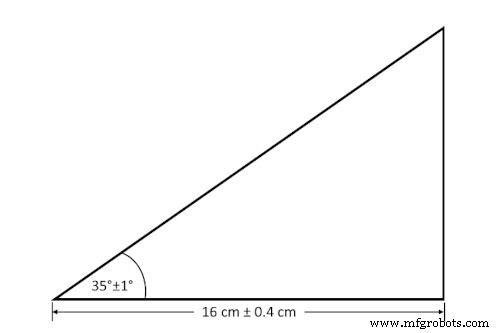
Example #1: Equal Bilateral Tolerances
- Angle: 34° – 36°
- Length: 15.6 cm – 16.4 cm
When a designer requires an asymmetric band—larger on one side than the other—they apply an unequal bilateral tolerance, also known as an unequally disposed tolerance. The figure below demonstrates this case.
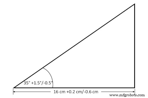
Example #2: Unequal Bilateral Tolerances
- Angle: 34.5° – 36.5°
- Length: 15.4 cm – 16.2 cm
When one side of an unequal tolerance is zero, the specification turns into a unilateral tolerance.
What Is Unilateral Tolerance?
A unilateral tolerance limits deviation in only one direction relative to the nominal value—either positive or negative. Though less common than equal bilateral tolerances, they are indispensable for mating parts that must fit precisely.
Consider a pinhole that accepts a pin with a maximum diameter of 1 inch. The hole must have a minimum diameter of 1 inch; otherwise, the pin would be too large to fit. By setting unilateral tolerances on both the hole and the pin, the parts’ tolerances never overlap, guaranteeing a proper fit.
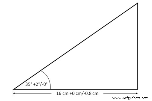
Example #3: Unilateral Tolerances
- Angle: 35° – 37°
- Length: 15.2 cm – 16.0 cm
Other Design Tolerance Types

Beyond unilateral and bilateral tolerances, engineering incorporates several geometric tolerances—straightness, circularity, flatness, parallelism—to keep parts within acceptable shape limits. These controls are vital when a long rod must pass through a series of aligned holes, for example.
Compound tolerance accounts for cumulative variation across multiple dimensions. In Example #3, the hypotenuse’s compound tolerance is approximately 19.3 cm ± 0.7 cm.
Takeaways

Unilateral and bilateral tolerances provide engineers with clear, actionable acceptance criteria for quality control. They also enable the creation of custom go/no‑go gauges that streamline inspections.
For deeper insights into tolerance notation, consult ISO or ASME GD&T standards. If you need precision machining that meets the highest quality benchmarks, Gensun’s CNC services deliver.
Industrial Technology
- Effective Strategies for Reducing Scope 3 Emissions
- Why Modernizing Your Fleet Cuts Costs and Boosts Sustainability
- Manufacturing Today and Tomorrow: Insights, Trends, and Future Outlook
- Understanding Strain Wave Gears (Harmonic Drives): Compact, High‑Reduction Solutions for Robotics
- Unlocking Success: Baselining Manufacturing Data Before Deploying New Technologies
- Choosing the Right Battery Connection: Series, Parallel, and Series‑Parallel Configurations
- VSync Explained: How It Works and When to Enable or Disable It
- Building Tomorrow: Fast Radius's Mission to Innovate
- Understanding Chemical Compatibility of Additive Manufacturing Materials: A Practical Guide
- PCB Material Costs Surge Across the Supply Chain