


Brown‑Out Reset Explained: Safeguarding Microcontrollers Against False Power‑Downs
Brown‑Out Reset is a key feature that enhances microcontroller reliability by preventing unstable operation when power dips below safe levels. This article delves into how BOR protects against power‑quality issues and illustrates a real‑world case where enabling BOR resolved a silent failure in an astronomical sensor array.
Understanding Brown‑Out Reset
A “brown out” occurs when a microcontroller’s supply voltage briefly falls below the threshold required for reliable operation. Most modern MCUs include a protection circuit that detects this drop and automatically resets the device, ensuring a clean start once power returns. This action is known as a Brown‑Out Reset (BOR). A more advanced feature, Low‑Voltage Detect (LVD), monitors multiple voltage levels and can trigger an interrupt before a reset is issued.
BOR is typically enabled via a control‑register bit. When a reset is triggered by a brown‑out event, a status flag is set and preserved across the reset (provided the voltage never falls too low). The firmware can then inspect this flag to log the event or perform additional recovery steps.
Without BOR, a steadily dropping supply—such as a draining battery or a deteriorating regulator—can leave the microcontroller in an indeterminate state. The following diagram illustrates the danger zone that BOR replaces with a reset.
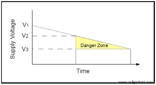
In the figure, V1 is the nominal supply voltage, V2 marks the boundary where reliable operation can no longer be guaranteed, and V3 is the point where the MCU stops functioning entirely. The interval between V2 and V3 is the “danger zone.” A BOR threshold set above V2 ensures that any excursion into this zone triggers a reset, which is preferable to unpredictable behavior.
Finding an Unexpected Use for Brown‑Out Reset (The Hard Way)
I once designed a module for a PIC microcontroller that powered 18 voltage regulators feeding +5V to 18 light sensors. Twelve such modules controlled 204 sensors in an adaptive optics system on the Mauna Kea telescope. The schematic of a single module is shown below.
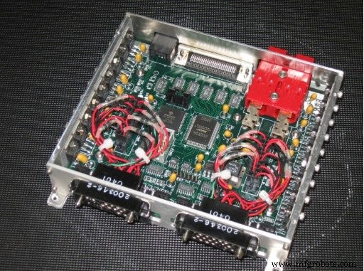
Pictures courtesy of the Subaru Telescope
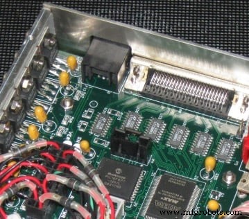
The PIC sits near the board’s center, while the regulators mount along the enclosure’s walls. All circuitry—including RS‑485 transceivers and control signals—runs from the same +5V rail. The module’s RS‑485 line drivers and receivers are critical to its operation, as shown in the close‑up.
Bench and laboratory tests were flawless. The first field test at the telescope, however, revealed a mysterious failure: after a power cycle, about half the modules lost RS‑485 communication. Debugging at 13,589 ft revealed corrupted variables and a non‑functional serial interface, even though the MCU was running.
Here’s a simplified schematic of the problem.
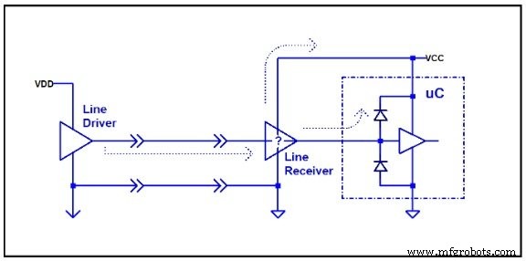
The module’s VCC drops to zero, but the remote RS‑485 line drivers remain powered. Their outputs effectively become weak voltage sources that bleed through the module’s interface and into the MCU’s ESD protection diodes, keeping the core supply in the danger zone. When the module’s own supply is restored, the MCU does not receive a proper power‑on reset; it starts executing code under corrupted conditions.
Temperature differences between the laboratory and the telescope’s colder coolant likely exposed the issue only in the field. The fix was surprisingly simple: enable BOR in firmware. The reset ensured the MCU started from a clean state, and the problem disappeared. The time to write the report and convince stakeholders far exceeded the time to implement the solution.
False Power‑Down Explained
The following diagram depicts the generic scenario.
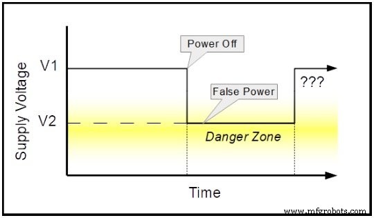
When the main supply is turned off, other sources—such as line drivers or stray capacitance—keep the MCU’s voltage in the danger zone. This phenomenon is sometimes called “False Power.” Without BOR, the MCU may not trigger a power‑on reset, leading to unpredictable behavior after the next power cycle.
In my case, a Microchip PIC16F877‑20I/L (industrial version, –40 °C to +85 °C) operated at 16 MHz with a recommended supply range of +4.0 V to +5.5 V. While the module’s V1 stayed at +5 V, the false power level V2 dropped to ~+1.5 V under telescope conditions—well above the VDD start voltage (0 V) but below the BOR threshold (+3.7 V to +4.35 V). Consequently, the MCU stayed alive in the danger zone and never performed a proper reset.
Enabling BOR raised the reset trigger above the false power level, ensuring the MCU reset correctly. The underlying mystery remains: why did the modules tolerate many power cycles in the lab? It appears that the lab environment lacked the stray voltage sources that appeared in the field.
Conclusion
Microchip’s AN607 labels this situation as a “False Power‑Down.” Such conditions can arise from external signals, multiple supply rails, or slow‑discharging capacitors. Even with BOR enabled, a sufficiently high false power source applied directly to a GPIO can cause issues, especially in low‑power designs where BOR consumes significant energy compared to deep‑sleep modes.
Designers should therefore consider false power scenarios when choosing between BOR, LVD, or alternative power‑management strategies.
— The article is supported by real-world testing and the latest microcontroller datasheets.
Industrial Technology
- Exploring 6G: The Future of Ultra-Fast Connectivity
- Copper Brazing Explained: Techniques & Tips for Strong, Reliable Connections
- Understanding Welding Porosity: Causes, Detection, and Prevention Techniques
- Understanding a Fathom: What It Is and How Deep It Measures
- 10 Common Injection Molding Defects & Prevention Tips
- Expert Strategies for Eliminating Non-Wetting Defects in PCB Production
- Preventing Poor Solder Wetting: Proven Techniques for Reliable Joints
- Eliminate Void Defects in Solder Joints: Expert Prevention Guide
- Understanding Cavitation in Hydraulic Pumps & Proven Prevention Techniques
- Understanding Welding Porosity: Causes, Symptoms, and Prevention Techniques