Smart Home Automation with Bluetooth Connectivity
Components and supplies
 | | × | 1 | |
| | Bluetooth Low Energy (BLE) Module (Generic) |
| × | 1 | |
| | × | 1 | |
About this project
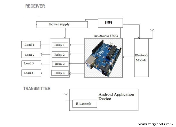
Circuit design: The circuit design of Home Automation based on Arduino and Bluetooth is very simple and is explained below. The Bluetooth module has 4 – pins: VCC, TX, RX and GND. VCC and GND are connected to 5V and ground from Arduino UNO. The Bluetooth module works on 3.3V and it has an on board 5V to 3.3V regulator. The TX and RX pins of the Bluetooth module must be connected to RX and TX pins of the Arduino. when connecting RX of Bluetooth to TX of Arduino (or any microcontroller as a matter of fact), we need to be careful as the pin can tolerate only 3.3V. But the voltage from TX or Arduino will be 5V. So, a voltage divider network consisting of 10K and 20K resistors are used to reduce the voltage to 3.3V approximately.
Working:When the power is turned on, the connection LED on the Bluetooth module starts blinking. We need to start the “Bluetooth Controller” app in our smartphone and get connected to the Bluetooth module. If the pairing is successful, the LED becomes stable.Now, in the app, we need to set different keys for different loads and their corresponding value that must be transmitted when that key is pressed. The following image shows a set of keys to control 4 loads and an additional key to turn off all the loads.
The app can be downloaded from the link below:
https://drive.google.com/open?id=1nG3IVv4Sfq7oxc6i7c2kwBkIuNLsXeZx
Code
codeArduino
#include <SoftwareSerial.h>
SoftwareSerial BT(0, 1); //TX, RX  pins of arduino respetively
String command;
void setup()
{
 BT.begin(9600);
 Serial.begin(9600);
  pinMode(2, OUTPUT);
  pinMode(3, OUTPUT);
  pinMode(4, OUTPUT);
  pinMode(5,OUTPUT);
}

void loop() {
  while (BT.available()){  //Check if there is an available byte to read
  delay(10); //Delay added to make thing stable
  char c = BT.read(); //Conduct a serial read
  command += c; //build the string.
  }
  if (command.length() > 0) {
    Serial.println(command);
  if(command == "light on") //this command will be given as an input to switch on light1
  {
    digitalWrite(2, HIGH);
  }
  else if(command == "light off") //this command will be given as an input to switch off light1 simillarly other commands work
  {
    digitalWrite(2, LOW);
  }
  else if (command == "lamp on")
  {
    digitalWrite (3, HIGH);
  }
  else if ( command == "lamp off")
 {
   digitalWrite (3, LOW);
 }
  else if (command == "fan on")
 {
   digitalWrite (4, HIGH);
 }
  else if (command == "fan off")
 {
   digitalWrite (4, LOW);
            }
    else if (command == "open")
 {
   digitalWrite (4, HIGH);
 }
  else if (command == "lock")
 {
   digitalWrite (4, LOW);
 }
  else if (command == "all on") //using this command you can switch on all devices
 {
   digitalWrite (2, HIGH);
   digitalWrite (3, HIGH);
   digitalWrite (4, HIGH);
 }
  else if (command == "off")//using this command you can switch off all devices
 {
   digitalWrite (2, LOW);
   digitalWrite (3, LOW);
   digitalWrite (4, LOW);
 }

command="";}} //Reset the variable
Schematics