


Rough Terrain Forklift: Design, Manufacturing, and Future Innovations
Background
A forklift is a mobile machine that uses two prongs, or forks, to lift and place loads in positions that are otherwise hard to reach. Forklifts fall into two main categories: industrial and rough‑terrain. Industrial models are common in warehouses and truck or train loading docks; they feature small tires for paved surfaces and are powered by internal‑combustion engines running on gasoline, diesel, or propane. Some smaller units use electric motors and batteries. Rough‑terrain forklifts, as the name suggests, are engineered for unpaved, uneven ground. They are widely used on construction sites and in military applications. Equipped with large, pneumatic tires and powered by gasoline, diesel, or propane engines, they come in two configurations: a vertical tower that lifts loads straight up, or a telescoping boom that lifts loads out from the machine’s base.
The rough‑terrain forklift’s lineage dates back to 1946, when a two‑pronged lift attachment was mounted on a power buggy or tractor chassis. This early model could lift about 1,000 pounds (454 kg) to a height of 30 inches (76 cm). By the mid‑1950s, vertical‑tower models had capacities of 2,500 pounds (1,135 kg) and lift heights of up to 30 feet (9 m). In 1958 the first four‑wheel‑drive rough‑terrain forklift appeared, boasting a 6,000‑pound (2,724 kg) capacity at 22.5 feet (7 m) or 3,000 pounds (1,362 kg) at 35 feet (11 m). The 1962 launch of the first telescoping‑boom model enabled operators to place loads out from the base, both above and below grade—critical in cluttered construction sites.
Advances through the 1970s and 1980s refined telescoping‑boom designs, introduced automatic hydraulic frame leveling for enhanced stability, and, following OSHA mandates, improved operator cabs and controls. Today, rough‑terrain forklifts handle pallets of concrete block, plywood stacks, and roof beams. The largest models feature telescoping booms with lift capacities up to 10,000 pounds (4,540 kg), vertical reaches of 40 feet (12 m), and forward reaches exceeding 25 feet (7 m). Low‑profile designs allow passage through openings as low as 8 feet (2 m). Steering options include two‑wheel, four‑wheel, and four‑wheel crab configurations.
Raw Materials
Frames, cabs, booms, and bodies are typically fabricated by the manufacturer, primarily from steel. Steel or aluminum castings and forgings may also be used. Non‑metallic guides—often nylon plastic—are incorporated in boom assemblies. The remainder of the components—engine, transmission, axles, wheels, tires, brakes, seat, gauges, lights, backup alarm, hoses, and hydraulic cylinders—are purchased as finished parts and installed during manufacturing. Bulk supplies of hydraulic fluid, lubricants, and fuel are added as needed.
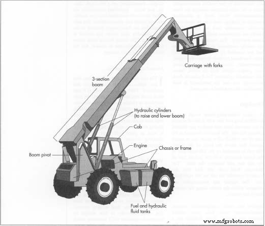
Design
A standard telescoping‑boom rough‑terrain forklift is long and low, featuring a pair of front wheels and a rear pair. The boom pivots at the rear, rising several feet above the frame. The cab sits on the left side, low between the tires; the hydraulic and fuel tanks are on the right. The engine and transmission occupy the centerline of the chassis. Variations include single versus dual hydraulic cylinders for boom lift, side‑to‑side frame leveling that tilts the frame up to 10° to compensate for uneven ground, and swingable fork attachments that pivot 45° left or right for precise load placement.
The Manufacturing Process
Manufacturing proceeds in functional groups—hydraulics, powertrain, electrical, chassis, and boom. Subassemblies are built separately before final integration. The typical workflow is:
- Materials Preparation: Raw steel (sheet, plate, bars, tubes) is cut to size using CNC plasma or oxy‑acetylene torches for thicker plates (up to 0.75 in) and shearing for thinner sheets. Fixtures ensure dimensional accuracy.
- Welding: Components are tack welded, then fully welded by CNC machines that precisely control weld placement, temperature, and feed rate to meet American Welding Society standards.
- Shot Blasting: Parts are cleaned in a rotating chamber where metal pellets remove scale and weld splatter, preparing surfaces for paint.
- Painting: All exposed surfaces—except the boom until after telescoping assembly—receive a detergent wash, acid wash, and phosphorus coating for adhesion. Electrostatic paint is applied in a booth, followed by oven baking for a hard finish.
- Subassembly: The boom is built from 2–4 telescoping sections of hollow steel tubes, each equipped with hydraulic cylinders, chain drives, nylon guides, and stop plates. Separate teams handle cab, chassis, powertrain, and electrical wiring.
- Final Assembly: Axles, tires, brakes, engine, transmission, and hydraulic components are installed. The boom assembly is mounted, hydraulic cylinders are connected, and all hoses and electrical links are sealed. Fluids are filled, and warning decals are applied.
- Start‑up and Testing: Each forklift undergoes a 1.5‑hour functional test with actual loads, with final adjustments made as needed.
- Shipping: Completed units are trucked or rail‑shipped, typically three forklifts per load to reduce freight costs.
Illustration of Frame Fabrication
The frame, cab, boom, and body of a telescoping‑boom rough‑terrain forklift are usually fabricated by the forklift manufacturer. The remainder of the parts are usually purchased as finished products and are installed by the manufacturer. Purchased products include the engine, transmission, axles, wheels, tires, brakes, seat, gauges, lights, backup alarm, hoses, and hydraulic cylinders.
Quality Control
Rigorous inspections and tests ensure compliance with safety standards. Critical components are checked on coordinate measuring machines for dimensional accuracy, alignment, and geometry. Welders and CNC welding equipment must hold American Welding Society certification. Visual inspections accompany fabrication and assembly steps.
Full forklift designs undergo ASME stability testing to determine safe load limits at various reach distances. For example, a forklift with a 10,000‑pound (4,540 kg) capacity may lift that weight only to 20 feet (6 m) and 8 feet (2 m) forward. At a 25‑foot (7.6 m) forward reach, the load capacity drops to 2,000 pounds (908 kg) without outriggers and 3,250 pounds (1,476 kg) with outriggers. Warning labels and charts in the cab clearly communicate these limitations.
The Future
Attachments such as winches, articulated booms, and rotating fork carriages are expanding the utility of rough‑terrain forklifts, enabling precise placement of materials on roof slopes or in tight interior spaces. Future enhancements are likely to include built‑in safety features: load‑reach management systems that use pressure sensors to automatically restrict reach based on real‑time load data, preventing over‑extension and potential boom failure or tipping.
Manufacturing process
- Tungsten Alloy: The Ultimate Forklift Counterweight Solution
- Premium Forklift Attachments: Top Sellers for Efficient Material Handling
- Mastering Forklift Forks: Essential Guide for Safety and Efficiency
- When to Replace Your Forklift Forks: A Practical Guide
- Top 5 Forklift Maintenance Tips for Peak Performance and Longevity
- How Regular Forklift Maintenance Boosts Safety and Reduces Downtime
- All-Terrain Cranes: How They Operate & Why They're Essential
- Essential Forklift Features for Optimal Shop Performance
- Choosing the Right Forklift: A Guide to Optimal Performance and ROI
- G71 Rough Turning Cycle One-Line Format: Simplify CNC Fanuc Programming