


Okuma G76 Fine Boring Cycle – Precise Hole Drilling & Parameter Setup
Okuma G76 Fine Boring Cycle
G76 Fine Boring Cycle
Programming
G76 X__Y__Z__R__Q__(I__J__) P__F__
Parameters
| Parameter | Description |
|---|---|
| X,Y | Coordinate values of hole position |
| Z | Hole bottom level |
| R | Point R level |
| Q | Shift amount (See the explanation below.) |
| I,J | Shift amount (See the explanation below.) |
| P | Dwell time at hole bottom |
| F | Feedrate |
Machining Sequence
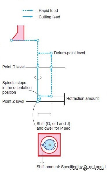
(1) Positioning along the X- and Y-axis at a rapid feedrate
(2) Positioning to the point R level at a rapid feedrate
(3) Boring to the point Z level at the specified cutting feedrate with the spindle rotating in the forward direction
(4) Dwelling at the point Z level for P seconds, retracting by the amount set at SHIFT DIRECTION AND AXIS IN G76, G87 of NC optional parameter (FIXED CYCLE), then spindle stop in the orientation position. After that, the tool shifts by the shift amount, Q, to the direction the tool bit moves away from the machined workpiece inner surface.
(5) Returning to the return point level at a rapid feedrate
(6) Tool shifts back in the bit direction by the shift amount, Q, then the spindle starts rotating in the clockwise direction.
Details
Retraction amount at the point Z level
The amount the Z-axis retracts upward from the point Z level is set at SHIFT DIRECTION AND AXIS IN G76, G87 of the NC optional parameter (FIXED CYCLE).
Shift amount
a. Q is used to specify the shift amount if the cycle axis is fixed as the Z-axis by the setting at SHIFT DIRECTION AND AXIS IN G76, G87 of the NC optional parameter (FIXED CYCLE). The value set must always be positive. The direction for shift motion, +X, -X, +Y, or -Y, should be set using a parameter beforehand. Note that a Q value is modal data and address Q is also used in the G73 and G83 cycles. A Q value is given priority over I and J values.
b. I and J are used to specify the shift amount when the plane is selected using G17, G18, or G19. The relationship between the plane selecting G code and the addresses to be used is shown below.
G17 I, J
G18 K, I
G19 J, K
For addresses I, J, and K, all values are set as incremental values. The shift direction is always defined in the machine coordinate system.
c. If the shift amount is not specified by Q, or I and J, an alarm occurs.
CNC Machine
- Mastering CNC Fanuc G76 Threading Cycle: Comprehensive Guide
- Mastering Tapered Threading on Fanuc G76 CNC Lathes
- Mastering G76 Thread Cycle: CNC Thread Cutting Guide
- Effortless CNC Threading with Mach3 Turn G76 Canned Cycle
- Fanuc G76 Fine Boring Cycle: Video Demo & CNC Mill Tutorial
- Master Fanuc G76 Fine Boring Cycle for Precision CNC Milling
- Mastering the Fanuc G85 Boring Cycle: Precision Hole Drilling Explained
- Fanuc G86 Boring Cycle – Precision Hole Drilling with Repeatable Depth Control
- Precision Sharp Edge Rounding Using Okuma G76 G‑Code
- ECS G85 Boring Cycle – Optimized Tool Return & Precision Drilling