



Reducing CNC Machining Complexity: Key Challenges and Proven Optimization Strategies
Deep, Narrow Grooves and Structures with Tight Clearances
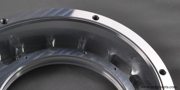
Parts such as heat sinks and valve bodies often feature deep, narrow grooves and densely packed thin‑walled ribs to cut weight and increase heat dissipation. In CNC machining these features pose several critical issues:
- Long‑edge cutters are required for deep slots. When the tool overhang exceeds its diameter, elastic deflection and chatter can occur, leading to dimensional inaccuracies and surface defects.
- Limited space in narrow grooves hampers chip evacuation, increasing the risk of chip jams and tool breakage.
- Coolant penetration into deep, tight areas is difficult, causing heat buildup that deforms the part and compromises precision.
Optimization Techniques
- During design, widen slots or reduce depth so that the tool diameter to depth ratio stays within acceptable limits.
- Use high‑rigidity, small‑diameter tools or long‑edge cutters combined with firm clamping supports.
- Increase coolant flow or incorporate chip‑evacuation channels.
- If redesign is not possible, adopt a staged machining approach: rough machining removes bulk material, followed by finish machining to achieve final tolerances.
Structures with Small Radii and Incomplete Corner Clearance
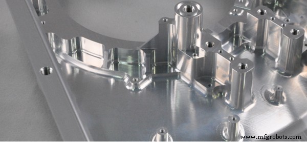
Internal corner radii that are too small often necessitate EDM or manual finishing. The main challenges are:
- Tool diameter limits: Small‑radius corners require tiny tools, but deep cavities demand long tools whose minimum diameter is constrained by rigidity.
- Tool path residue: If the tool radius exceeds the specified corner radius, material remains, creating a “dead knot.”
- Additional process steps: Unclearable corners require EDM, adding clamping errors and cycle time.
Optimization Techniques
- Increase the internal radius where design allows, enabling a single machining pass with standard tools.
- Apply helical or circular arc feed patterns at corners to avoid sudden direction changes that induce chatter.
- Redesign problematic areas into external corners or add process notches to simplify machining.
Thin‑Walled Structures
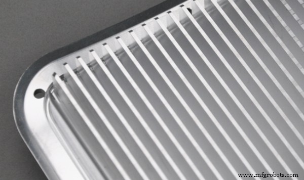
Thin‑walled parts are lightweight but susceptible to deformation and vibration under cutting forces:
- Poor rigidity: Thin walls lack stiffness, leading to elastic deformation during machining.
- Clamping challenges: Excessive clamping force warps the part; insufficient force leads to unstable positioning.
- Resonance risk: Low natural frequencies can match cutting frequencies, degrading surface quality.
Optimization Techniques
- Add ribs or temporary supports during design and remove them after machining.
- Use auxiliary supports such as vacuum suction cups or low‑melting‑point alloy fillers.
- Separate roughing and finishing; during finish use light cuts, high spindle speeds, and rapid feed rates.
Case Study: Machining Optimization of an Electric Truck Heat‑Sink Housing
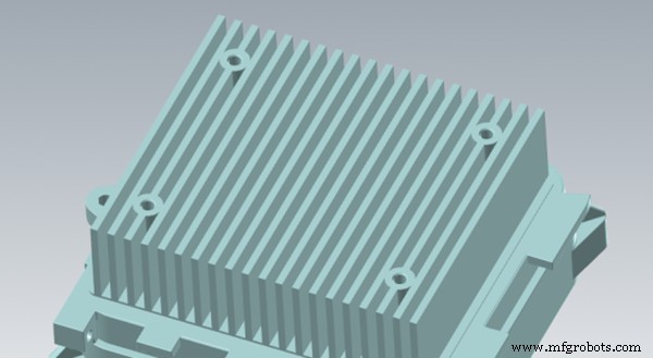
The heat‑sink housing, made of ADC12 aluminum and measuring 159 × 135 × 67 mm, features a dense fin structure with deep grooves to dissipate power‑train heat. Initial analysis revealed several bottlenecks:
Design‑Related Machining Challenges
1. Unreasonable Deep, Narrow Grooves
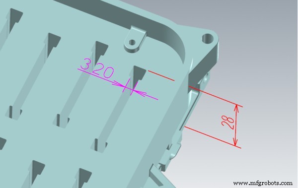
Groove width of 3.2 mm and depth of 28 mm required a 3 mm long‑fluted cutter with an overhang of >29 mm, resulting in poor rigidity, high tool breakage risk, extended cycle time, and difficulty achieving Ra 1.6.
2. Extremely Small Corner Radius
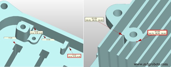
The cavity depth of 28 mm required a 3 mm cutter, but its R 1.5 radius could not machine the design’s R 0.5 corners, leaving material that would need EDM clearing.
3. Thin Local Wall Thickness
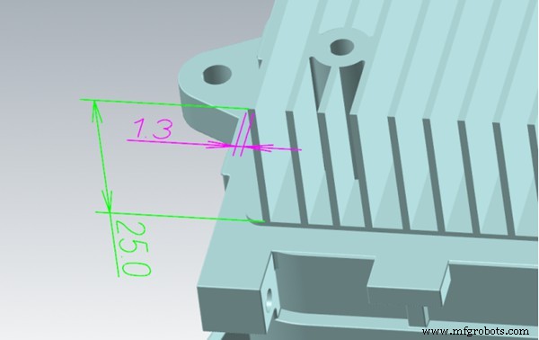
Fins only 1.2 mm thick and 25 mm high were prone to vibration and deflection during milling, compromising dimensional stability.
Optimized Machining Plan and Results
1. Stepped Groove Design
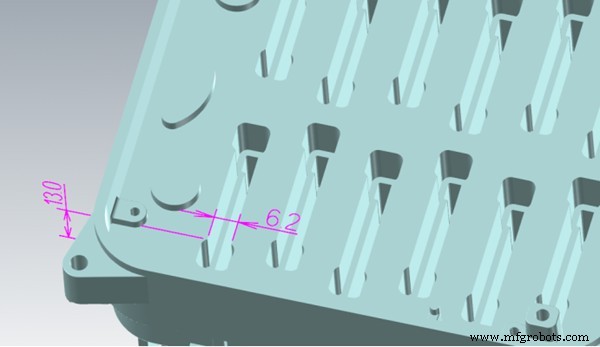
The 28 mm groove was split: the lower 15 mm retained a 3 mm width; the upper 13 mm widened to 6.2 mm. First a 6 mm cutter machine the upper section, then a 3 mm cutter handles the deep part. Each tool operates within a safe length‑to‑diameter ratio, enabling a 3‑fold increase in cutting parameters. Total cycle time dropped from 2.8 h to 1.1 h, and tooling cost fell 60 %.
2. Enlarged Corner Radii to Eliminate EDM
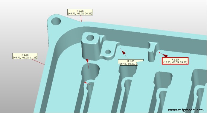
Increasing the cavity bottom radius to R 1.55 and the stepped corner to R 3 allowed direct machining with 3 mm and 6 mm flat‑bottom end mills, removing the EDM step and improving dimensional consistency.
3. Thickened Thin Walls
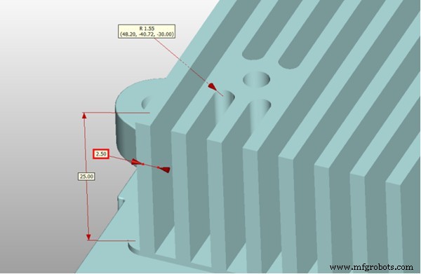
Wall thickness was increased from 1.3 mm to 2.5 mm, suppressing deflection and achieving ±0.05 mm tolerance.
Machining Performance Comparison
| Item | Before | After | Improvement |
|---|---|---|---|
| Single‑part machining time | 6.5 h | 3.2 h | 51 % reduction |
| Tool consumption | 8–10 tools/part | 4–6 tools/part | 40 % reduction |
| EDM process | Retained | Eliminated | 2.5 h saved |
| Surface roughness | Ra 1.6–3.2 | Ra 0.8–1.2 | Significant improvement |
Manufacturing Optimization Recommendations
- Tool accessibility assessment: Keep slot depth below five times the tool diameter to avoid excessive overhang.
- Fillet radius selection: Design internal corners with radii that match standard tool sizes to eliminate EDM or manual finishing.
- Fin structure adjustment: Where feasible, replace tightly spaced deep slots with stepped configurations and increase wall thickness or reduce fin count to improve rigidity and machining feasibility.
With extensive experience in complex geometries and tight tolerances, WayKen delivers CNC machining solutions that integrate DFM feedback and advanced strategies. Our approach reduces cycle times, tooling costs, and scrap rates while ensuring consistent, high‑quality parts.
Modern mechanical designs increasingly rely on complex structures. Ignoring CNC machining limitations can lead to processing difficulties, cost overruns, and scrap. By addressing tool accessibility, thin‑wall vibration, chip evacuation, and corner‑radius issues early in design, only minor adjustments can yield major improvements in manufacturability and cost efficiency.
CNC Machine
- Jig vs. Fixture in CNC Machining: Essential Differences & Practical Uses
- Why First-Time Customers Should Choose CAD/CAM Manufacturing
- Understanding Sherline CNC Lathe: Key Components & Their Functions
- CNC Milling Subprogram: Seamless Arc Integration with G02, G03, and G41 Commands
- Creating Threaded Holes: Essential Tapping Guidelines
- Large 2030 CNC Router Machine Arriving in Bratislava – Reliable Export from Blue Elephant CNC
- Easy Setup and Operation Guide for the SYNTEC Control System
- AI-Driven CNC Machining: Boosting Precision, Speed, and Production Efficiency
- Master Nesting Labels in Heidenhain Conversational Programming – Step-by-Step Exercise
- Hard Machining Demystified: Key Concepts and Best Practices