


Expert Guide to Correctly Sizing Hydraulic Flanges
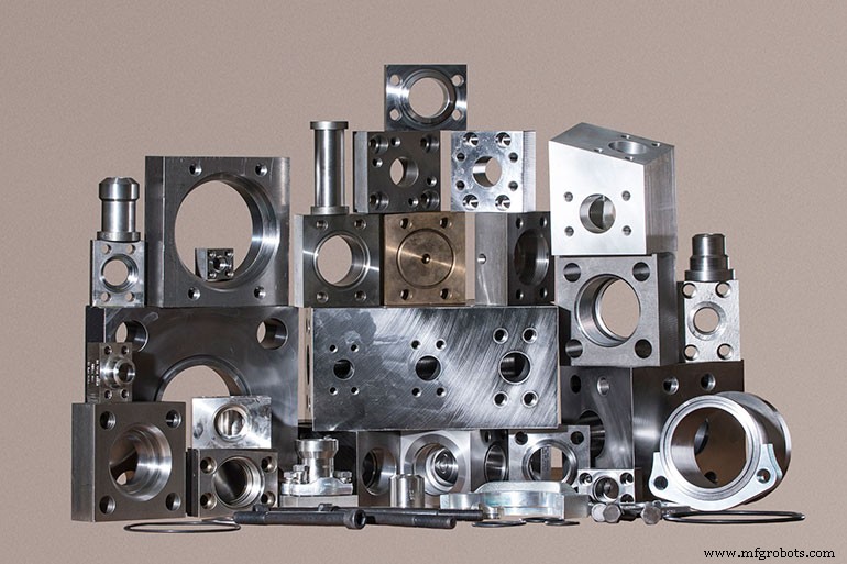
Hydraulic flanges may appear simple, but they are critical pressure‑containing junctions that can make or break system reliability. Proper sizing impacts performance, maintenance, safety, and long‑term cost.
Understand the Application First
At its core, a flange connects hydraulic components to piping or hose. However, specifying the right one requires far more than a nominal size. According to Robert Mackey, General Manager of Main Manufacturing Products Inc. and SAE J518 authority, engineers need nine key data points:
- Pad size
- Bolt size and type
- Material
- Connection type
- Connection size
- Pressure rating
- Geometry
- Flange type
- Special features and origin
SAE J518 flanges dominate worldwide, aligning with ISO 6162. Yet many systems also use DIN, JIS, CETOP, or proprietary designs depending on the manufacturer and region.
Don’t Rely on Nominal Size Alone
Nominal sizing (e.g., “1‑in.” or DN25) is a naming convention, not an exact dimension. Engineers must verify real measurements to avoid mismatches, especially when sourcing an existing flange.
Precision Measurement Is Essential
Visual similarity between standards can hide critical differences in bolt patterns or dimensions. Mackey recommends measuring bolt hole spacing to within 0.005 in. (0.1 mm) using digital calipers: zero on the bolt hole diameter, then measure from outside‑to‑outside. Tolerances can vary by 0.010 in. or more, so even a visually acceptable flange may fail to seal or align under pressure.
Pressure Ratings Depend on Multiple Factors
Size alone does not dictate pressure capability. The screw size, O‑ring groove, bolt strength, flange geometry, material, and port design all play roles. In SAE systems, the port often limits the maximum pressure. Modifying geometry—such as removing a bolt—can reduce effective strength by 40–50% despite only a 25% reduction in bolt count.
Select the Appropriate Connection Type
Flanges can be welded (socket, butt, or special grooved), threaded (SAE straight, BSPP, BSPT, NPTF), or O‑ring boss. The fluid‑power industry increasingly prefers SAE straight‑thread O‑ring bosses for their superior leak resistance. Welded options demand careful attention to pipe schedules, tube OD, and regional standards; metric tubes may differ between German, Japanese, and Chinese specifications.
Geometry Influences Flow and Installability
Flange geometry shapes packaging and maintenance. Common configurations include inline connectors, elbows, run tees, branch tees, crosses, offset flanges, saddle welds, and connector blocks. Offset flanges preserve full flow in tight spaces; saddle welds allow mounting on pipe sides. These choices help reduce leak points and simplify servicing.
O‑Ring vs. Flat‑Face Design
Most modern hydraulic systems use O‑ring flanges because they provide reliable sealing under high pressure. O‑ring flanges feature clearance bolt holes and captive grooves that increase sealing force. Flat‑face companions use tapped holes and are less common but still used in specialized applications. Mismatched mating surfaces can prevent sealing entirely.
Material Selection Is Crucial for Reliability
Carbon steel, especially low‑carbon grades like 1018 or 1025, remains the default for hydraulic flanges due to weldability and pressure performance. Alternative materials include stainless steel (304L, 316L), aluminum, Monel, Hastelloy, Inconel, and duplex stainless steel. Low‑carbon “L” grades reduce corrosion and weld degradation. Avoid using A36 structural steel for pressure boundaries.
Use Accessories to Simplify Design
Flange adapters, gauge port adapters, connector plates, spacers, reducers, reservoir adapters, and connector blocks can streamline systems and reduce downtime. Gauge port adapters enable direct pressure measurement without circuit redesign. Adapters can also convert between Code 61/62, rotate bolt patterns, or bridge inch/metric systems.
Correct Sizing Reduces Risk and Cost
Although flanges may seem routine, small specification errors can cause leaks, pressure loss, installation problems, or premature failure. Accurate sizing demands a holistic assessment of standards, pressure ratings, geometry, materials, and sealing methods—all evaluated together, not in isolation.
Industrial equipment
- Flood Irrigation Explained: How It Works and Its Pros & Cons
- Inside Houston's Recycling Center: How Your Waste Gets Sorted
- Boosting Production Efficiency with Rotary Transfer Technology
- Basic Oxygen Furnace Explained: The Engine of Modern Steel Production
- Electric Actuators: A Comprehensive Overview
- 5 Key Factors for Selecting the Right Plastic Hinges
- Sintered Friction Material: Definition, Benefits, and Industrial Applications
- Understanding Resin Adhesives: Composition, Uses, and Benefits
- Elastomeric Sealant Explained: Properties, Uses, and Benefits
- Essential Lathe Cutting Tool Types for Precision Machining