


Mastering Asynchronous Reset Synchronization in ASICs and FPGAs
Introduction
Asynchronous resets are the first line of defense in VLSI circuits, ensuring that all synchronous logic starts from a known state after power‑up. When the release of the reset signal is not carefully coordinated with the clock domains, designers can encounter intermittent, hard‑to‑track failures—especially in large, multi‑clock‑domain ASICs or in FPGAs where reset signals must be routed to millions of flip‑flops.
Challenges of Asynchronous Reset
Beyond synchronization, the sheer breadth of an asynchronous reset network poses a significant routing and area challenge. The problem scales with the number of clock domains and the required fan‑out, demanding solutions that resemble Clock Tree Synthesis (CTS) in terms of resource allocation.
Overview of the Series
- Part 1: Identification of synchronization issues and traditional mitigation approaches.
- Part 2 (this article): Advanced techniques for faster, more reliable reset distribution in ASICs and FPGAs.
- Part 3: Special‑case solutions and practical tips.
2. Asynchronous Reset Timing Convergence Techniques
Large designs with high‑latency reset networks often struggle with the short clock cycles required by modern logic. Conventional Static Timing Analysis (STA) optimisation can become prohibitively expensive or even infeasible. Two proven techniques—reset pipelining and fan‑out limiting—offer a scalable path to convergence for both ASIC and FPGA implementations.
2.1. Asynchronous Reset Pipelining
The core idea is to trade a single‑cycle delay in reset release for a relaxed timing budget. By inserting an additional asynchronous‑set flip‑flop (P1) after each synchroniser, the SET and D inputs receive the same active‑high reset signal (RSTO). When RSTO deasserts, the setup and hold constraints of the new stage are satisfied as if it were a regular synchronous path.
click for larger image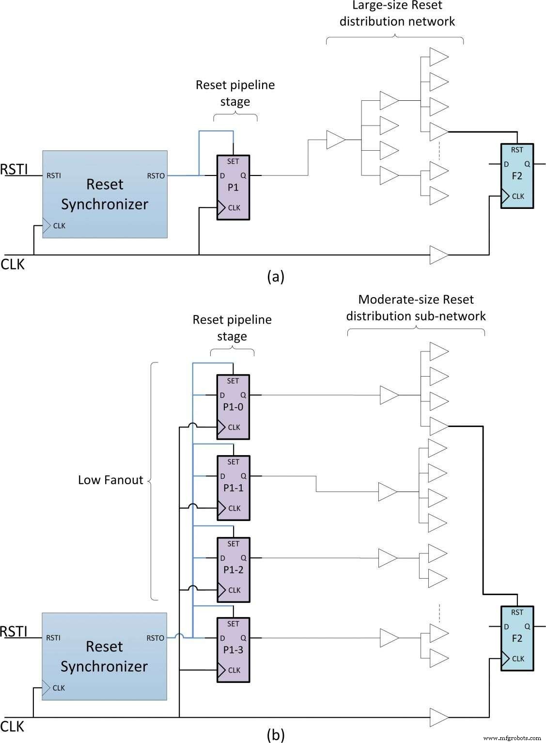
Figure 6: Asynchronous reset with pipelining (Source: vSync Circuits)
Functionally, the pipeline behaves like the standard reset tree described in Part 1, with the exception of a single‑cycle latency on release. This extra latency is usually negligible because it occurs only once per power‑up.
Design constraints play a pivotal role. While synchroniser flip‑flops must be protected against duplication (to avoid re‑convergence path issues discussed in Part 1), the P1 stage is constrained by a MAX_FANOUT rule. For example, a fan‑out of 8 is often sufficient for the synchroniser output. When the P1 stage reaches its fan‑out limit, the synthesis tool automatically duplicates the flip‑flop, creating several sub‑networks each with lower latency, as illustrated in Figure 6b.
Because the duplication is handled automatically, the technique scales seamlessly as the design grows or changes. If a single pipeline stage does not achieve timing convergence, additional stages (P2 – PN) can be inserted, each constrained by its own MAX_FANOUT value.
An illustration of this technique in a real design is shown in Figure 7. Here, the P1 stage—named PORT6—was duplicated roughly 40 times by the synthesis tool to satisfy the fan‑out constraint. Each sub‑network met the required timing, confirming the method’s effectiveness in large, complex designs.
click for larger image 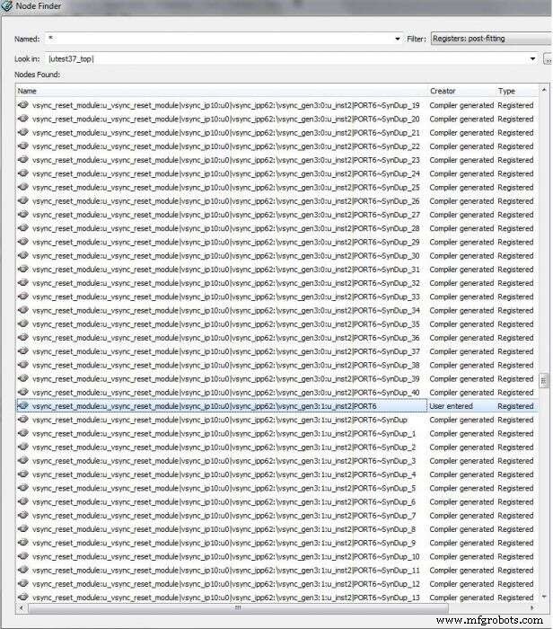
Figure 7: Example of asynchronous reset pipelining (Source: vSync Circuits)
Embedded
- Synchronizing Asynchronous Resets in ASICs and FPGAs: Challenges, Best Practices, and Advanced Solutions
- Anvo‑Systems and Mouser Forge Global Distribution Partnership
- Mouser Electronics Expands Global Reach with Inventek Systems Distribution Partnership
- Rutronik Becomes Exclusive European Distributor of AP Memory IoT RAM Under Global Agreement
- Subaru Adopts Xilinx FPGAs to Replace ASICs in Eyesight ADAS
- Albis Plastics Splits Distribution and Compounding Units Under Otto Krahn Group
- Expert Guide to Planning & Designing Power Distribution Systems
- Mastering Distribution Site Selection: A Strategic Guide for Executives
- Accurate Load Center & Panelboard Sizing: NEC & IEC Guidelines
- Enhance Safety & Efficiency in Gas Distribution Systems