


ARMv8 Firmware Architecture: Key Components and Boot Flow in Server Systems
Since its debut in 2011, the ARMv8 architecture has become ubiquitous in mobile devices. Forecasts from ARM Limited’s CEO projected that ARMv8 processors would capture up to 25 % of the global market by 2020. Naturally, software support has followed suit, evolving by inheriting the features and principles of the long‑established ARM ecosystem.
In the server arena, however, the landscape differs markedly. x86‑based servers have dominated for decades, while ARMv8 has only recently begun to carve out a niche in select enterprise segments. The novelty of ARM in this domain, coupled with the late adaptation of key standards such as ACPI and UEFI, has shaped the evolution of its firmware stack.
This article provides a high‑level overview of the firmware architecture that powers ARMv8 server systems. It is not exhaustive, and readers should note that new processor releases may introduce different technical solutions that warrant updated approaches.
Current firmware implementations for ARMv8 servers are modular, offering the advantage of reusing components across server and embedded firmware while isolating changes. Figure 1 illustrates the loading sequence and interactions between modules.
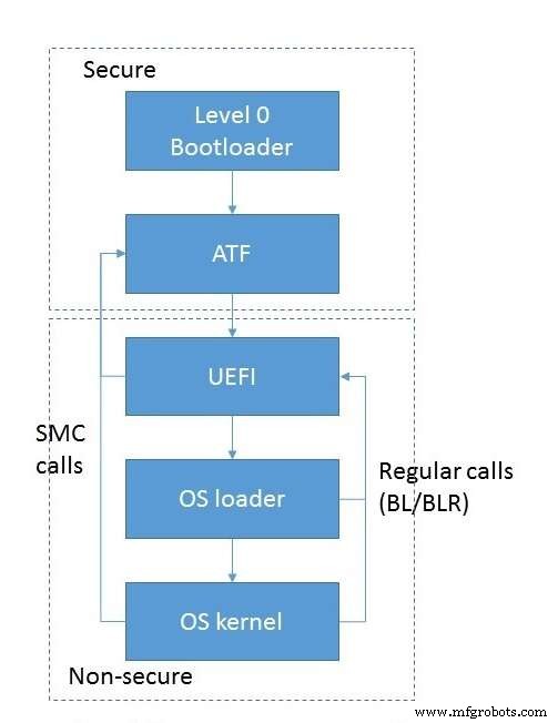
Fig 1. Module loading and interaction flow. (Source: Auriga)
Boot begins with the initialization of low‑level subsystems—RAM, inter‑processor communication, and so on—handled by a dedicated module that runs in EL3S mode immediately after the CPU powers on. This component enjoys the highest privileges and typically does not interact directly with the operating system.
Control is then passed to the ARM Trusted Firmware (ATF) module, also executing in EL3S. ATF may be invoked directly from the level‑0 loader or indirectly via a UEFI PEI module. The ATF chain consists of several stages, each activated at a specific point in the boot process.
The first stage, BL1, configures secure hardware resources. ARMv8’s hardware‑based isolation between trusted and non‑trusted memory mandates that BL1 establishes a secure environment: it programs memory and cache controllers, designates trusted vs. non‑trusted zones, and sets DMA filtering rules. Only devices with matching security attributes can access the corresponding memory regions. BL1 also builds the MMU translation tables and the exception vector table, particularly the Secure Monitor Call (SMC) handler that can delegate control to later stages.
Once BL1 finishes, it loads BL2 into RAM and hands off execution via the ERET instruction. BL2 runs in EL1S, a reduced‑privilege mode that protects the BL1 data and code from accidental modification. Its primary role is to load the remaining firmware stages (BL3 variants) and transfer control to them.
The third stage can comprise up to three sub‑stages, though BL3‑2 is often omitted. BL3‑1 is the trusted runtime code that the operating system interacts with during operation. It contains the SMC handler and implements the PSCI interface—standard calls for power management and core control—as well as vendor‑specific extensions. BL3‑2, if present, operates in EL1S and serves as a lightweight monitor for platform events such as timer interrupts or peripheral signals.
BL3‑3 is not part of ATF; it is a non‑secure image that takes over in EL2 mode. Typical examples include U‑Boot or a UEFI environment, both standard for server boot flows.
The ATF initialization sequence is summarized in Figure 2.
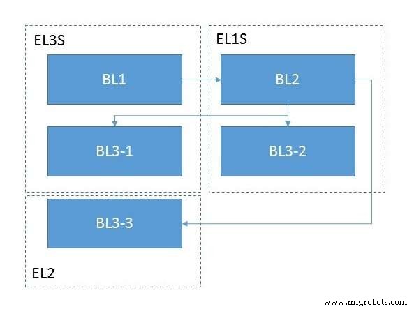
Fig 2. ATF module initialization. (Source: Auriga)
Embedded
- A Practical Taxonomy for Industrial Internet of Things (IIoT) Systems
- Optimizing IIoT Connectivity with the Industrial Internet Reference Architecture
- Robotics in the 21st Century: Distributed Systems, Telepresence, and Space Exploration
- Maxim’s Advanced LiDAR Module Enables 15 km/h Faster Autonomous Highway Driving
- Edge Computing: The Architecture Driving Tomorrow’s Intelligent Networks
- Mastering Control System Design: From Basic Panels to Advanced, Reliable Solutions
- Simplifying Control Architecture for Cartesian Robots to Boost Efficiency
- Cyber‑Physical Systems: The Driving Force Behind Industry 4.0
- Boost Productivity with Advanced Motion Control Systems
- Mastering Bill of Materials Creation in Manufacturing