


Prototyping Digital I/O with Microchip’s RN487x Bluetooth Module
Build reliable digital input and output peripherals using the RN487x Bluetooth module
In the second part of our three‑part series on Microchip’s RN487x Bluetooth modules, we’ll walk through creating a digital input (a switch) and a digital output (an LED). For background on module configuration, refer to the first article.
Project 1: RN487x Digital Input Switch
Our design follows a three‑step pattern:
- Hardware – a switch that generates the digital signal.
- Configuration – RN487x commands to allocate a database variable and map the pin to it.
- Application – a workstation script that reads the database value.
Digital Input Hardware
The input is a simple normally‑open switch (SW1). The RN487x provides internal pull‑ups, so a switch connected to ground on closure gives a clean two‑state signal.
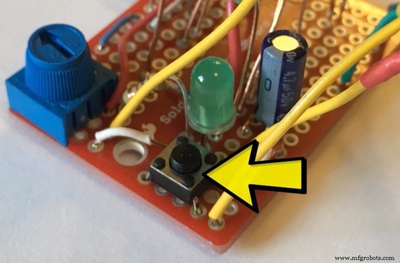
We use the RN4871, which supports single‑pin GPIO. The circuit can be powered from two AAA batteries or a coin cell. Additional components:
- C1: Bypass capacitor for power stability.
- R1, C2: Delay for processor reset at power‑on.
- J1: Serial port for configuration.
Digital Input Configuration
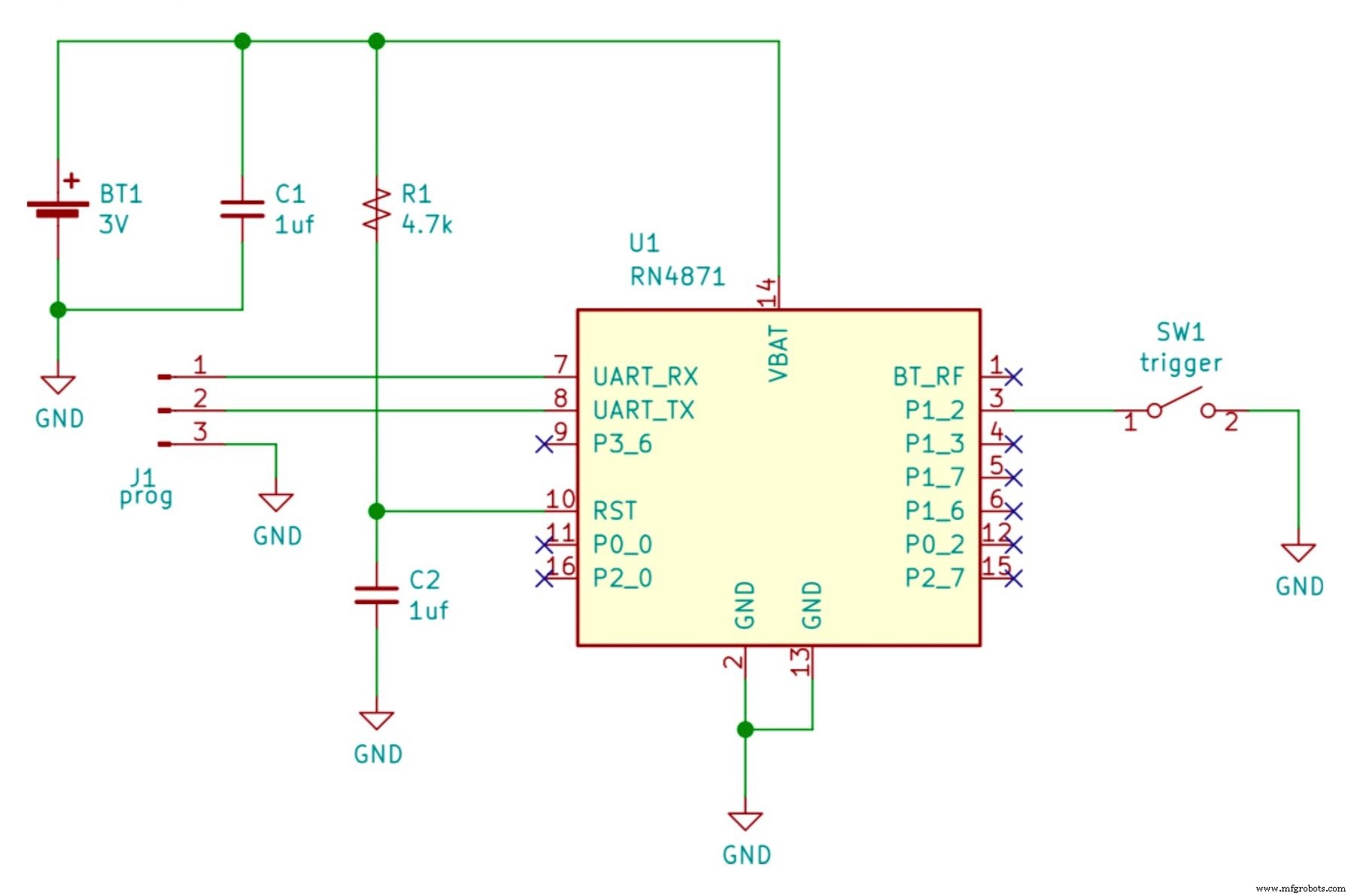
Ensure the module is in a known state before proceeding (see appendix for initialization). Create one service and one characteristic in the GATT database to represent the switch state:
PS,59c88760536411e7b114b2f933d5fe66
PC,59c889e0536411e7b114b2f933d5fe66,10,01
Here, PS creates the service, and PC creates the characteristic. The UUIDs are placeholders; generate your own following the UUID standard. The second parameter in PC (10) requests immediate notifications on value changes, and the third parameter (01) sets the value size to one byte.
The peripheral script configures the pin and handles events:
@PW_ON
SW,0A,09
@PIO1H
SHW,0072,01
@PIO1L
SHW,0072,00
Each method prefixed with @ runs on a system event:
PW_ON– on power‑on, sets P1_2 as a triggered digital input.PIO1H– on high transition, writes1to the database.PIO1L– on low transition, writes0to the database.
Digital Input Application
Use the switch.py Python script (link provided). Replace the sample MAC address with your device’s MAC. After powering the peripheral, run the script on a Bluetooth‑capable machine. The script connects to the device, listens for notifications, and prints each switch event. See the Linux setup guide in the appendix.
Key BLE feature: notifications—the peripheral pushes state changes to the client without polling.
Project 2: RN487x Digital Control (LED)
We apply the same three‑step pattern for an output:
- Hardware – an LED driven by the RN4871’s open‑collector GPIO.
- Configuration – create a database variable mapped to the LED pin.
- Application – a script that writes values to the database to turn the LED on or off.
Digital Control Hardware
The LED (D1) is connected as an open‑collector sink. The schematic follows the RN487x reference design.
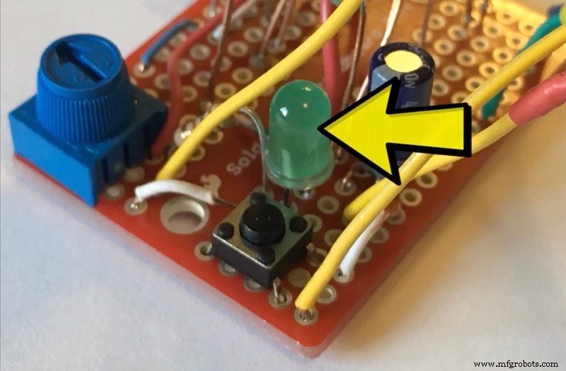
Components:
- C1: Power bypass capacitor.
- R1, C2: Reset delay.
- J1: Serial port.
Digital Control Configuration
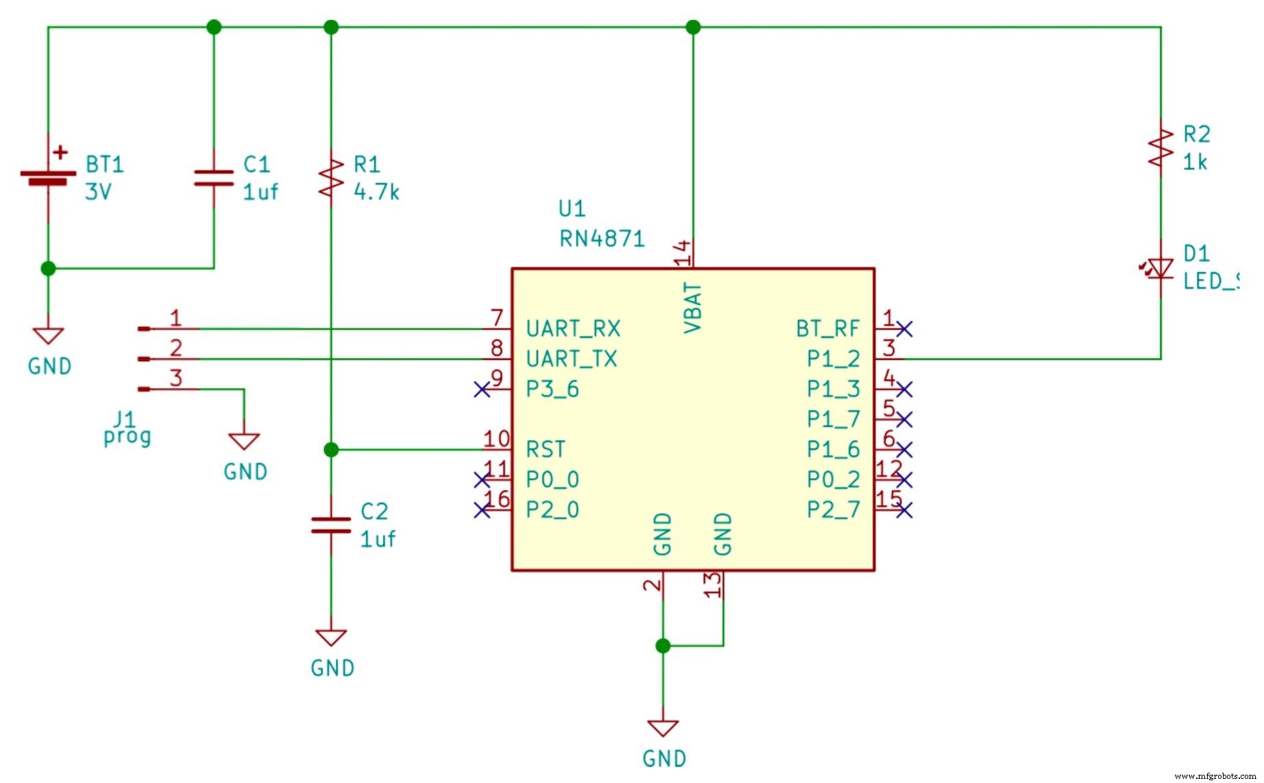
Initialize the module as described in the appendix. Create a single service and characteristic:
PS,59c88760536411e7b114b2f933d5fe66
PC,59c889e0536411e7b114b2f933d5fe66,08,01
Here, 08 indicates the peripheral must confirm writes, and 01 sets a one‑byte value. The script handles client connections:
@CONN
|O,08,72
When a client connects, the command associates the database variable with the LED pin (bitmask 08) and the characteristic handle (72). Subsequent writes by the client toggle the LED.
Digital Control Application
Run light.py (link provided) after replacing the MAC address. The script connects to the peripheral, then sends a new value every second to turn the LED on and off. The script logs progress and illustrates the handle association feature.
Watch the full demonstration in the accompanying project video.
Next Steps
This concludes part 2 of our RN487x series. Part 3 will tackle analog sensors and controls, and provide additional resources applicable to all projects.
Internet of Things Technology
- C# Fundamentals: Input and Output Essentials
- Mastering Microchip RN487x Bluetooth Modules for Low‑Power Peripherals
- Elevate Your Operations: Leveraging IoT Tank Monitoring for Safer, Smarter, and More Profitable Petroleum Management
- Seamlessly Control Arduino Uno via ESP8266 WiFi Module and Blynk App
- WiFi vs. Bluetooth: Key Differences and Similarities Explained
- 8 Proven Methods to Test Capacitors with Digital & Analog Multimeters
- Precise Power Measurement Using Digital and Analog Multimeters
- Accurate Voltage Measurement with Digital and Analog Multimeters – A Step-by-Step Guide
- Measuring AC and DC Current with Digital and Analog Multimeters: A Practical Guide
- Lean Digital: Definition, Benefits, and How to Seamlessly Integrate It