


Mastering Microchip RN487x Bluetooth Modules for Low‑Power Peripherals
Learn how to configure Microchip’s RN487x family of Bluetooth modules for your low‑power peripheral projects.
If you’re building a compact, energy‑efficient device, Bluetooth is almost always the communication choice of record. Over the years the standard has matured, and today a wide range of ready‑to‑use modules provide a complete system‑on‑chip (SoC) that meets the needs of many peripherals. A popular example is Nordic’s nrf52840, which combines a 32‑bit processor, a multi‑protocol Bluetooth radio, and a full complement of I/O interfaces such as GPIO, PWM, USB, SPI, and I²S.
While powerful, these SoCs can be daunting: the learning curve and development time required to integrate the embedded firmware are significant. For many common use cases—remote sensing or control with only a handful of analog or digital channels—a simpler, more focused solution is often preferable.
Enter the RN487x family from Microchip. The two modules in this family—RN4870 and RN4871—offer multiple concurrent bi‑directional digital and analog channels while keeping the design footprint and firmware effort minimal. Each module stores a compact configuration in its non‑volatile RAM, enabling you to tailor the peripheral’s functionality to your exact requirements. Importantly, the modules remain fully compliant with the Bluetooth Low Energy (BLE) standard, ensuring seamless pairing with modern smartphones and other BLE clients.
In this three‑part series, we’ll walk through creating a fully functional Bluetooth‑enabled peripheral for four typical tasks: a digital sensor, a digital control, an analog sensor, and an analog control. Each example includes a reference circuit, the precise RN487x configuration steps, and a simple Python script that demonstrates how to interact with the peripheral from a Linux host. The scripts are thoroughly documented so you can easily embed the peripherals as subsystems in larger designs.
Design Overview
Below is a graphical illustration of the “analog sensor” example, highlighting the key interfaces in red.
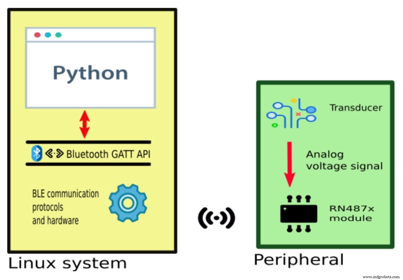
A representation of a Linux system communicating with a peripheral
We’ll build three core components for this example:
- The peripheral hardware that provides the sensor signal—an analog transducer in this case, generating a varying voltage.
- The host application that presents the data to the user—our Python script.
- RN487x configuration that maps the physical signal to the GATT database used by the host.
Component Selection
The RN487x family offers two variants: RN4870 and RN4871. They differ mainly in pin count and available I/O types. Below is a reorganised pin‑budget table to help you decide which chip best suits your project.
There are three I/O pin categories on the modules:
| Type | Description |
| ADC | Analog input: converts a voltage into a numeric value. |
| PWM | Analog output: generates a square wave whose frequency and duty cycle are set by two numbers. |
| DIO | Digital input or output: a high or low level represents logic 1 or 0. |
RN4870

Image from the RN487x datasheet
| Pin Name/Capability | P1_0 | P1_1 | P1_2 | P1_3 | P2_2 | P2_3 | P2_4 | P2_5 |
| ADC | x | x | x | x | ||||
| PWM | x | x | ||||||
| DIO | x | x | x | x | x |
RN4871
Image from the RN487x datasheet
| Pin Name/Capability | P1_2 | P1_3 |
| ADC | x | |
| PWM | ||
| DIO | x | x |
These tables clarify that if your design only needs a single analog input and no PWM outputs, the RN4871 is the leanest choice. For projects requiring multiple signals or PWM, the RN4870 is the appropriate selection. In the analog sensor example, we use the RN4871 and connect the sensor to pin P1_2.
GATT (Generic Attribute) Profile Layer of the BLE Protocol Stack
Before writing the host application, it’s essential to understand the GATT API that will mediate communication between the host and the peripheral.
All BLE devices expose a GATT database that the peripheral (server) populates. The host (client) uses GATT calls to read or write values identified by handles or names. Typical Python GATT operations look like this:
gatt_rq.connect()
# Write a value to a characteristic handle
gatt_rq.write_by_handle(vh_light, str(bytearray([8])))
The first call establishes a connection; the second writes data that is immediately reflected on the peripheral’s outputs. The GATT API is supported by iOS, Android, Windows, and Linux. Our examples use Python on Linux for broad compatibility.
Module Configuration
To bridge the physical signal to the GATT database, you must program the RN487x’s NVRAM with two key configuration blocks:
- Characteristic Definition: Allocates database space and assigns unique identifiers for each value.
- Pin Binding: Maps physical I/O pins to database characteristics, enabling automatic data conversion.
The RN487x uses a lightweight command language for configuration. Refer to the appendix for details on establishing a console connection and issuing configuration commands. After programming, the module’s NVRAM might look like this:
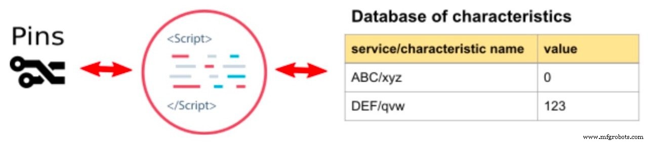
All configuration values reside within a two‑level hierarchy of services and characteristics—useful when scaling to multi‑sensor or multi‑control designs.
That concludes part one of our three‑part RN487x tutorial series. Parts 2 and 3 will cover digital input, digital control, analog sensor, and analog control implementations. Part 4 will discuss advanced topics applicable to all examples.
Below is an appendix that outlines how to configure the modules before diving into the detailed projects.
Using a Console Connection to Configure the RN487x
Power the module and establish a serial link to your workstation. Each demo circuit includes a 3‑pin “prog” jumper exposing RX, TX, and GND. If you need guidance, an excellent guide is available here.
Launch a terminal emulator. The miniterm utility (bundled with many Python distributions) is a good choice. In a shell, start it like this:
python -m serial.tools.miniterm --eol LF /dev/ttyUSB0 115200
The default baud rate of 115200 is suitable for the RN487x.
Switch from DATA to COMMAND mode by typing three dollar signs ("$$$")—you won’t see the characters, but the prompt changes to:
CMD>
Try pressing d followed by Enter; the module will echo its status:
CMD>
BTA=D88039F80080
Name=RN_BLE
Connected=no
Authen=2
Features=0000
Services=00
CMD>
Enable echo if you want to see the key you type: press + and Enter:
CMD> ECHO ON
CMD>
Creating a new GATT service is as simple as issuing a single PS command, for example:
CMD> PS,59c88760536411e7b114b2f933d5fe66
AOK
Project configurations also require multi‑line scripts. Begin a script with WW, enter each line, and finish with Esc to commit:
CMD> ww
@CONN
|O,08,72
AOK
CMD>
Common Initialization of the Module
When reusing an RN487x module across projects, previous configuration can interfere with new uses. Perform the following cleanup steps before each example:
- Erase any existing script.
- Enable script processing.
- Erase existing service/characteristic definitions.
- Remove any special functions from the pin you’ll use (e.g., P1_2).
- Reboot the module.
Execute the command sequence below:
CMD> WC
AOK
CMD> SR,0040
AOK
CMD> PZ
AOK
CMD> SW,0A,00
AOK
CMD> R,1
Rebooting
Linux Setup Required for Running Example Python Scripts
Hardware
Ensure your host system has BLE hardware (Bluetooth 4.0 or newer). If you need a USB adapter, we recommend one based on the Qualcomm CSR8510, available here.
Software
The example scripts have been tested on Debian 10 and should work on other Debian‑based distributions such as Ubuntu. Two Python packages are required that are not installed by default:
python-bluez– provides access to the Bluetooth stack.gattlib– offers Python bindings for GATT operations (install viapip).
Installing gattlib builds an ELF library, so you’ll need build tools and libraries. A helper script that installs all dependencies is available here. After downloading, make the script executable and run it.
References
- RN487x Datasheet
- RN487x User Guide
- GATT API in Windows
- GATT API in iOS
- GATT API in Python
Stay tuned for the next parts of this series, where we’ll build the complete digital input and digital control examples.
Jump to projects 1 and 2: building a digital input and digital control.
Internet of Things Technology
- Analog vs Digital Sensors: Types, Applications, and Practical Examples
- Harnessing Cellular IoT and Bluetooth LE: A Synergistic Approach for Next‑Gen Connectivity
- Bluetooth Mesh Design Choices: Module vs. Discrete Device
- Contrinex 2020: Cloud-Ready Sensors & Bluetooth Light Curtains for Safety
- Reading Analog Sensors with Raspberry Pi and Zabbix: A Step‑by‑Step Guide
- Prototyping Digital I/O with Microchip’s RN487x Bluetooth Module
- From Edge to Cloud: Mastering IoT Data Pipelines
- Digitalisation in Food & Beverage: Enhancing Safety, Traceability, and Efficiency
- Edge Computing & IoT Strategy Insights from IoT World 2019
- 6G Takes Off: Milestones, Satellites, and Global Telecom Momentum