


Designing with Markforged Composite Filaments: Minimum Feature Sizes for Optimal Reinforcement
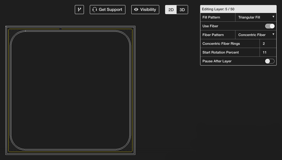
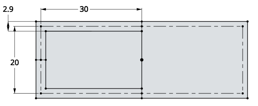
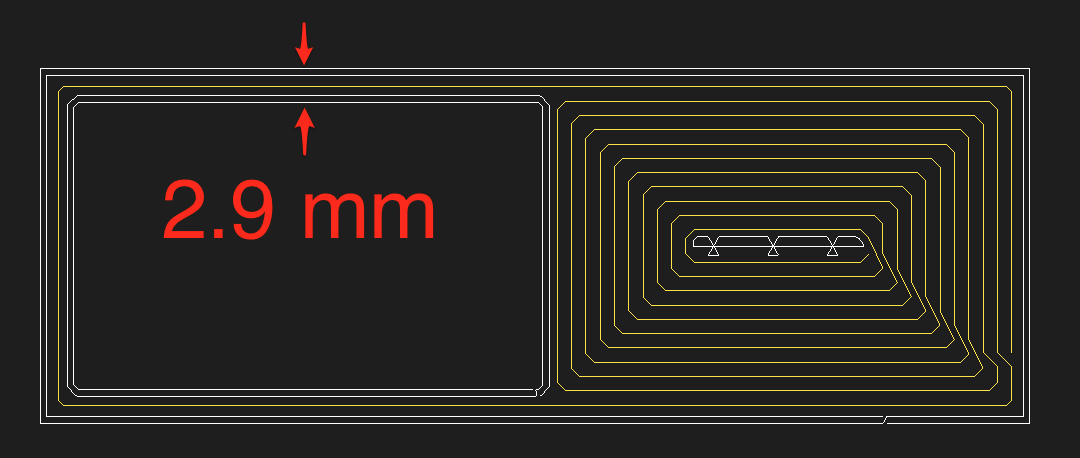
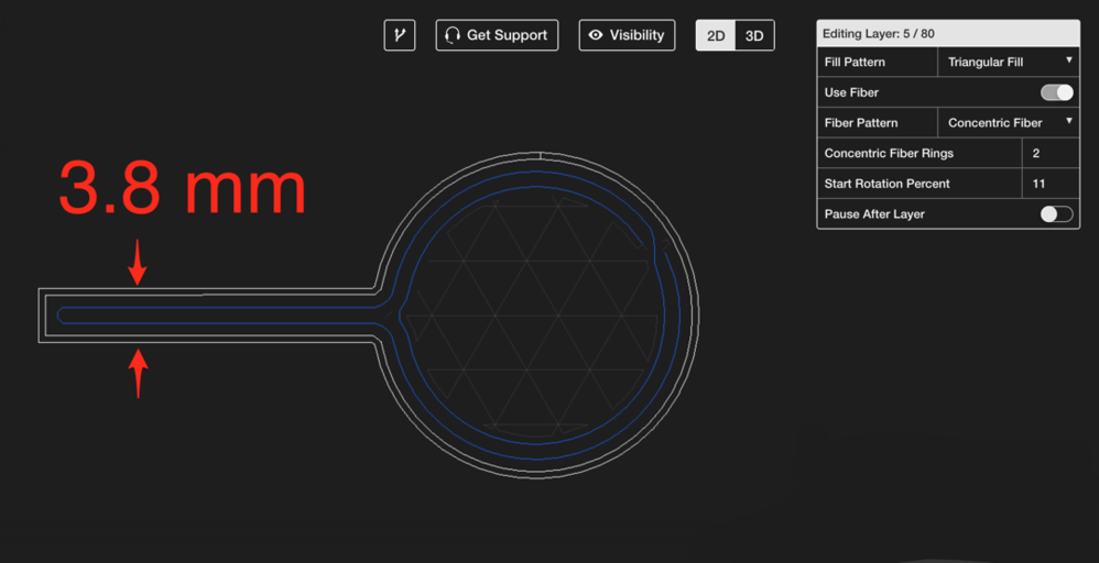
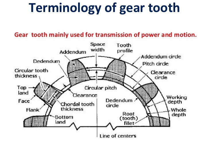
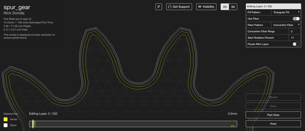
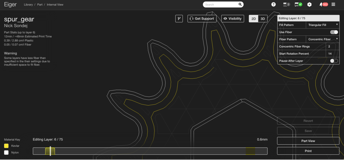
Markforged composite filaments deliver exceptional strength and stiffness to 3D‑printed parts, but like any manufacturing technology, they perform best when the design is tailored to their capabilities. Understanding the minimum feature sizes that can be reinforced is essential for creating reliable, high‑performance components. To achieve optimal reinforcement, composite filaments must be able to flow between the outer nylon shells of a part. When a section is too narrow, the filament cannot be laid down correctly, compromising structural integrity. In Eiger, the design tool, use a Concentric Fiber pattern to create a single, continuous fiber path that threads through the narrow geometry. Alternatively, combine an Isotropic Fiber pattern with at least one concentric ring if additional reinforcement is needed elsewhere. When a continuous loop is possible, a single 1 mm‑wide fiber path can be laid across the section. Adding the two nylon shell layers on either side raises the minimum reinforced thickness to approximately 2.9 mm. Designers should therefore incorporate at least this dimension into any thin region that requires fiber reinforcement. Features that protrude from a main body—such as vanes, turbine blades, or propellers—often connect at only one end. In these cases, the filament must double back to form a concentric ring, requiring two 1 mm‑wide paths. Consequently, the minimum width for a projecting feature is 3.8 mm. When reinforcing gear teeth or sprocket cogs, the fiber must span from the root to the tip. For teeth that taper to a width below 3.8 mm, full‑length reinforcement is impossible, which can leave a localized weak spot. While the component will still outperform a pure‑plastic version, designers should aim for tooth profiles that maintain the 3.8 mm minimum at the tip to ensure consistent strength. For smaller gears, fiber can still reinforce the bulk of the tooth, but designers should be aware that the tip may remain comparatively weaker. Ready to prototype industrial‑strength parts? Request a demo of the Mark Two today and experience the difference of fiber‑reinforced 3D printing.Reinforcing Thin Sections
Handling Projecting Features

Practical Applications: Gears and Sprockets
Key Takeaways
3D printing
- Eiger’s New Brim Feature: Reliable, Warp‑Free Prints for Thin Parts
- Optimizing 3D Printed Part Strength with Efficient Fiber Routing – Part 1
- A Custom Carbon‑Fiber Phone Amplifier by MarkForged Engineer Dan Topjian
- Dan Topjian’s Carbon‑Fiber Business Card Holder – A Markforged Showcase
- Introducing the Composite Cable Clamp by MechEngineerMike: A Durable, Kevlar‑Reinforced Solution
- High-Performance 3D-Printed Tripod with Continuous Carbon Fiber Reinforced Legs – STL Files & Build Guide
- Markforged Elevates Drone Performance with Carbon‑Fiber 3D Printed Parts – Part 1
- Precision Machining of Long Parts Using Vertical Clamping
- Manufacturing Trends 2021: Part 2 – Insights from Make UK
- Manufacturing 2021: Key Trends and Insights – Part 1 with Make UK