


Optimizing 3D Printed Part Strength with Efficient Fiber Routing – Part 1
Editor's Note: This is Part 1 of a comprehensive series on efficient fiber routing with the Markforged 3D printer. If you’re new to the Markforged platform and want to learn more, contact us here. After finishing this post, explore Part 2 for advanced techniques.
Types of Fiber Fill
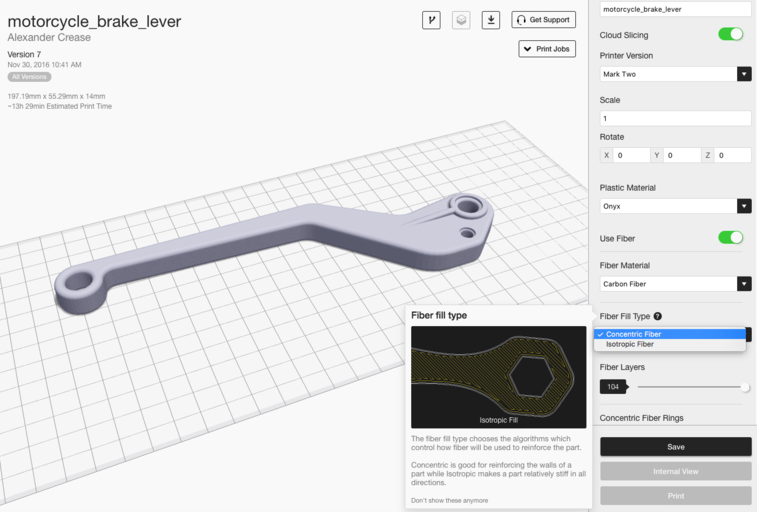
Our high‑strength 3D printers provide two distinct fiber‑fill strategies for reinforcing parts: Isotropic Fiber and Concentric Fiber. These options can be applied globally on the Part View page or on a layer‑by‑layer basis in the Internal View page. Each fill type offers unique reinforcement characteristics—see below for details. If you don’t have a Markforged printer, you can still test these tactics with an Eiger trial.
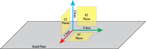
First, some standard naming conventions so that everyone is on the same page. I’ll be referring to strength in different axes and planes frequently, so use this key as a guide:
Concentric Fill Reinforcement
Concentric Fill traces a specific number of shells within the outer contours of your part, reinforcing the part’s walls against bending around the Z axis. Because the print‑head follows the outer curvature as it spirals inward, the movement is non‑linear and the head must slow to maintain accurate tool‑path tracking, which increases build time. You can specify how many concentric rings you want to trace, giving you precise control over fiber usage per layer.
Isotropic Fill Reinforcement
Our continuous‑fiber printers can also produce an Isotropic Fiber fill pattern that mimics the unidirectional layers of a traditional laminated composite. Each layer consists of a single angular orientation of parallel fibers, with 180° turns at the edges. Subsequent isotropic layers are automatically rotated by 45° by Eiger, though custom orientation patterns are possible (see Part 2). Isotropic Fiber resists bending in the XY plane because any applied force generates tensile load on at least some fibers, which excel in tension. It can also be used to build sandwich panels that boost torsional strength on that plane.
By default, isotropic fiber adds two concentric rings around the outer surface, ensuring a smoothly reinforced exterior. While this method reinforces the entire plane of each layer, it is fiber‑ and time‑intensive, and may not always be necessary for achieving strong parts.
Basic Fiber Routing Techniques
With these two fiber‑routing options in your toolbox, you can combine them to target specific load paths, saving material and print time while maximizing strength.
Single Sandwich Panel
A sandwich panel is a common composite lay‑up that enhances torsional stiffness around the surface that the composite sheet forms. Think of it as the composite equivalent of an I‑beam, where the top and bottom layers carry the most bending stress. If your part will experience torsion in the XY plane, a sandwich panel will significantly increase torsional strength.

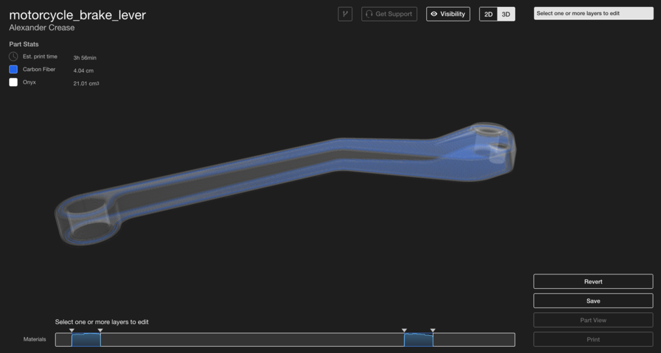
Our software automatically generates a sandwich panel when “Use Fiber” is selected, but it works best on symmetrical parts where the top and bottom layers match. In the example, the brake lever’s top surface is a small extrusion, so we manually added fiber beneath the largest top surface instead. Generally, the sandwich panel should consist of layers with similar cross‑sectional areas.

To keep the sandwich balanced, ensure an equal number of isotropic layers on the top and bottom surfaces you wish to reinforce. An uneven sandwich produces asymmetric bending stiffness, which can cause warping or premature failure. The more layers you place on each side and the further apart the sandwich, the stronger the part. Fibers placed in the center of the part have a smaller impact on bending strength, so fully filling the interior is unnecessary.

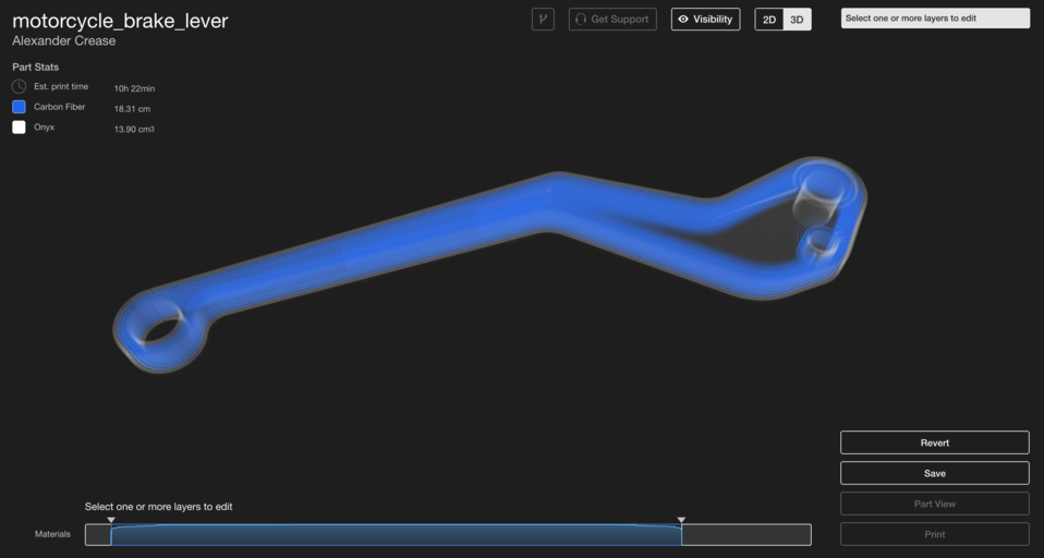
Fiber Perimeter
While sandwich panels strengthen the XY plane, a fiber perimeter strengthens the part around the Z axis. By applying Concentric Fill on every layer, you increase wall stiffness against bending about the Z axis. This approach mirrors the engineering practice of using C‑channels or tubes instead of solid blocks to reduce weight while preserving strength.
To set up a fiber perimeter, select Concentric Fill on the layers you wish to reinforce. Increasing the number of concentric rings or extending concentric fill to more layers boosts Z‑axis strength. In the brake lever example, we reinforced every layer with three concentric rings to maximize stiffness, while leaving the interior unreinforced because it experiences the least bending.
Shelling
When a part must resist flexing in all directions—or when load paths are uncertain—combine sandwich panels with intermediate fiber shells. The resulting design delivers flexural strength on every axis. For example, a motor bracket for heavy‑duty robotics requires robust reinforcement from all sides.
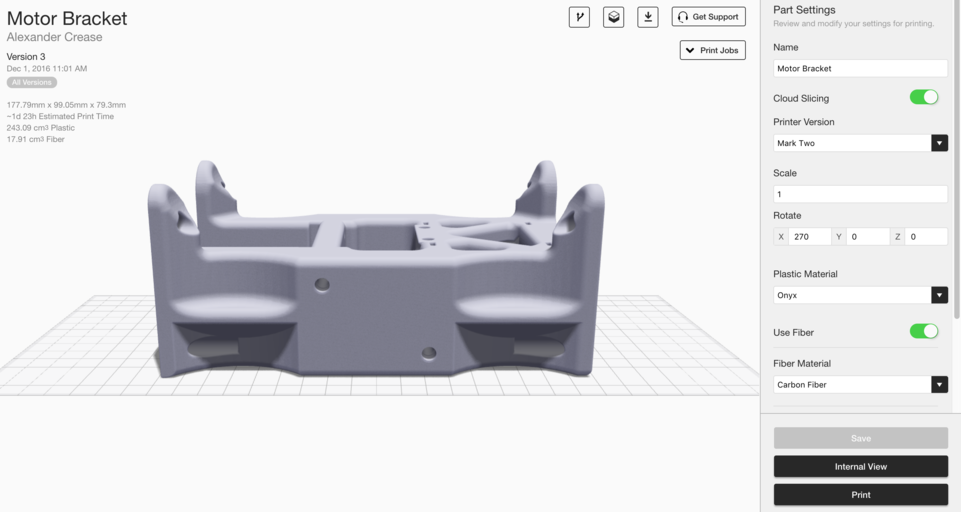
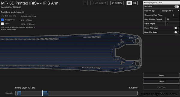
In this case, we selected 20 layers of isotropic sandwich paneling (10 per side) to achieve a very robust part. Because the top face has bolt‑hole extrusions, we repositioned the upper panel to sit beneath the top surface.
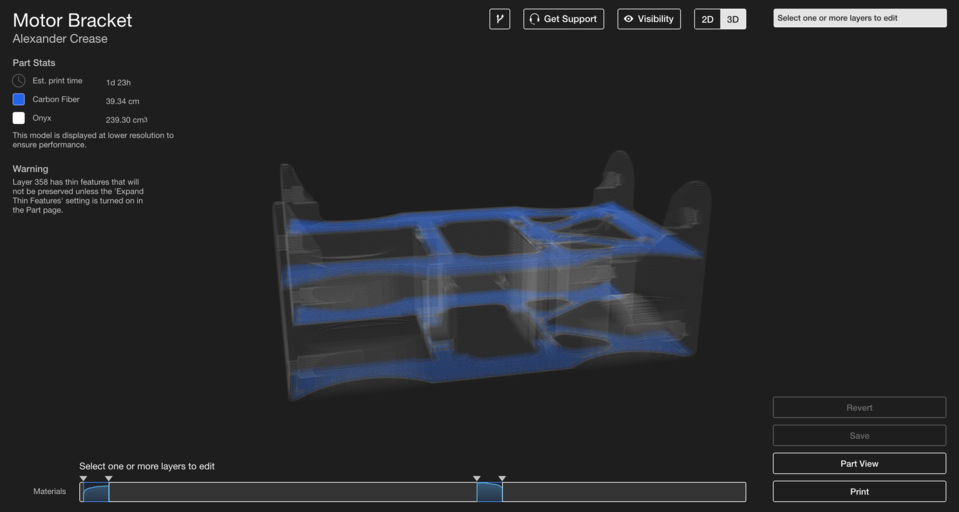
The bar at the bottom of the internal view allows you to monitor fiber usage for each section, normalized to the maximum amount. Here we see two separate fiber‑reinforced regions for a simple isotropic sandwich panel. By selecting the central region between the two panels, grouping it, and assigning Concentric Fiber Fill with two rings, we create an efficient, multi‑axis reinforcement strategy.
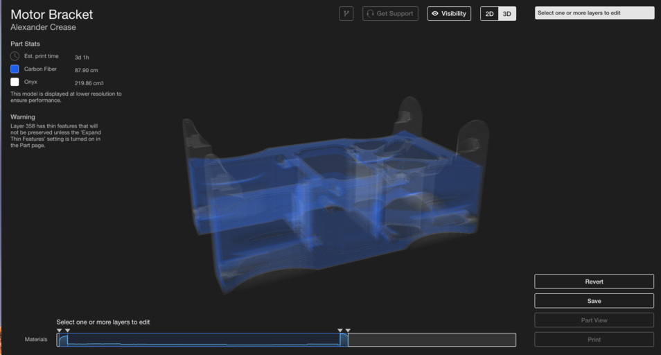
Through a clear understanding of each fill type’s reinforcement mechanism, you can apply simple yet powerful tricks—like the combination above—to enhance part performance and reduce print time without wasting fiber.
Interested in learning more? Request an Eiger trial to experiment with our software and fiber reinforcement options. Also check out Part 2 for advanced fiber routing techniques!
3D printing
- Coloring 3D‑Printed Parts with Wax Crayons: A Novel Post‑Processing Technique
- 3D‑Printed Carbon Fiber: A Superior Alternative to Aluminum Amid Global Shortages
- Elevating Quality Control: 3D‑Printed Tooling Enhances Manufacturing Precision
- In‑Process Inspection: Elevating 3‑D‑Printed Part Quality
- Professional Guide to Finishing and Painting 3D Printed Parts
- Advanced Fiber Routing Techniques for Markforged 3D Printing: Boost Strength & Performance
- High-Performance 3D-Printed Tripod with Continuous Carbon Fiber Reinforced Legs – STL Files & Build Guide
- Guaranteeing Dimensional Accuracy in 3D Printed Parts
- Enhancing the Strength of 3D Printed Parts: Proven Techniques
- Professional Guide: Dyeing 3D Printed Polyamide Parts for Vibrant Color and Durability