


Finite State Machine: Harnessing Feedback to Build Programmable Sequence Controllers
Feedback is a cornerstone of modern engineering, turning a straightforward circuit into a versatile control system. By embedding feedback loops—both negative and positive—designers can craft devices that adapt, stabilize, and perform complex logic with remarkable simplicity.
- Comparator + negative feedback → controllable‑gain amplifier
- Comparator + positive feedback → hysteresis‑enabled comparator
- Combinational logic + positive feedback → multivibrator
In process instrumentation, a measurement system coupled with negative feedback yields a closed‑loop controller that automatically corrects deviations from a setpoint.
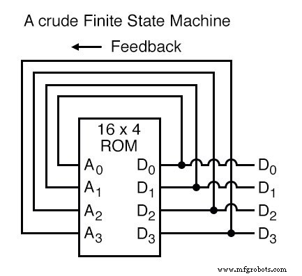
When a lookup table is programmed into a ROM and the data output is routed back to the address input, a new class of device emerges: the Finite State Machine (FSM). This structure uses stored data to dictate the next address, thereby generating a predefined sequence of outputs.
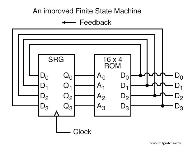
The fundamental idea is simple: each ROM address holds the address of the next state. To synchronize the sequence with a clock and avoid timing hazards, the data output is fed through a 4‑bit D‑type flip‑flop before it becomes the next address. The clock pulse ensures the machine transitions step by step.
An intuitive analogy is a row of post‑office boxes. Each box (address) contains a slip directing you to the next box (data). By arranging the slips in a desired order, you dictate the sequence of boxes opened and, consequently, the sequence of information read.
With 16 addressable locations, the FSM can inhabit 16 distinct stable states. The ROM is pre‑programmed with the next state for each address, and the machine advances on each clock edge.
One common application is generating an arbitrary count sequence, such as the 4‑bit Gray code:
Address  -----> Data          Gray Code count sequence:
0000   -------> 0001                 0   0000
0001   -------> 0011                 1   0001
0010   -------> 0110                 2   0011
0011   -------> 0010                 3   0010
0100   -------> 1100                 4   0110
0101   -------> 0100                 5   0111
0110   -------> 0111                 6   0101
0111   -------> 0101                 7   0100
1000   -------> 0000                 8   1100
1001   -------> 1000                 9   1101
1010   -------> 1011                10   1111
1011   -------> 1001                11   1110
1100   -------> 1101                12   1010
1101   -------> 1111                13   1011
1110   -------> 1010                14   1001
1111   -------> 1110                15   1000
Running through this table, the FSM starts at address 0000, reads the data 0001, and jumps to address 0001 on the next clock tick, and so on. When it reaches the final programmed state (address 1000), the stored data 0000 loops the sequence back to the beginning.
Expanding the ROM’s address lines and adding more data outputs further enhances flexibility. For example, a 5‑bit address ROM can encode two distinct count sequences—binary and Gray—controlled by an additional function line (A4). The following table illustrates this dual‑mode operation:
Address  -----> Data            Address  -----> Data
00000  -------> 0001            10000  -------> 0001
00001  -------> 0010            10001  -------> 0011
00010  -------> 0011            10010  -------> 0110
00011  -------> 0100            10011  -------> 0010
00100  -------> 0101            10100  -------> 1100
00101  -------> 0110            10101  -------> 0100
00110  -------> 0111            10110  -------> 0111
00111  -------> 1000            10111  -------> 0101
01000  -------> 1001            11000  -------> 0000
01001  -------> 1010            11001  -------> 1000
01010  -------> 1011            11010  -------> 1011
01011  -------> 1100            11011  -------> 1001
01100  -------> 1101            11100  -------> 1101
01101  -------> 1110            11101  -------> 1111
01110  -------> 1111            11110  -------> 1010
01111  -------> 0000            11111  -------> 1110
In this configuration, when A4 = 0 the FSM counts in binary; when A4 = 1 it follows the Gray code sequence. The programmer can define arbitrary sequences and even decide when the cycle restarts, making the FSM a fully programmable counting device.
Further enhancements are possible by using a ROM with additional address and data lines. A design might route D0–D3 back to A0–A3 for state feedback, while D4–D7 provide arbitrary outputs unrelated to the state. This expands the FSM’s capabilities beyond counting, allowing it to perform complex combinational logic that depends on both the current state and external inputs (A4–A7).
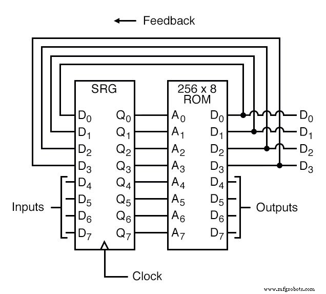
Moreover, the flip‑flop’s clock need not be a simple square‑wave generator; it can be tied to an external event, causing the FSM to advance only when a particular signal occurs. This event‑driven approach aligns the FSM’s operation closely with real‑world processes.
Thus, a ROM programmed with a lookup table, combined with feedback and clock control, realizes a true finite state machine. The program stored in ROM dictates the entire behavior, mirroring the theoretical Turing machine’s principle of a program dictating computation. This practical embodiment demonstrates the power of feedback, memory, and sequential logic to build sophisticated, reliable, and versatile digital systems.
Industrial Technology
- Expert Guide to Modern Change Machines: Design, Components, and Future Trends
- The Evolution and Manufacturing of Sewing Machines: From 19th‑Century Innovation to Modern Automation
- Pantyhose: The Ultimate Guide to Elegant Women’s Hosiery
- Designing a Finite‑State Machine in VHDL: A Practical Traffic Light Example
- Precision Meets Automation: Vision‑Guided Robotics Transforming Manufacturing
- Understanding Machine Turning: A Key Precision Machining Process
- Versatile Milling Machines: Cutting, Drilling, and More
- CNC Fundamentals: Mastering Computer Numerical Control
- Integrating Machine Learning into PLCnext Controllers
- JW Machine: Precision CNC Contract Manufacturing Services