


Understanding Look‑Up Tables: From ROMs to Advanced ALUs
In the previous chapter we explored digital memory devices, discovering how solid‑state storage cells can be precisely addressed using binary values. By driving the address lines of a ROM with specific binary patterns, we can retrieve stored data directly from its memory cells.
Imagine a ROM that has been pre‑programmed with a truth table for a particular logic function. The address lines then act as the function’s inputs, while the data lines deliver the corresponding outputs. With this setup, a single ROM chip can emulate any desired logic function—whether a half‑adder, a full adder, or an entirely different combinational circuit—without any physical rewiring.
Below is a 4 × 2‑bit ROM, configured to implement a half‑adder. When the A and B inputs are applied to the address pins, the ROM outputs the correct Sum (Σ) and Carry‑out (Cout) bits.
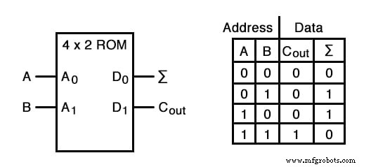
Unlike a gate‑based half‑adder, which processes the inputs through a fixed network of logic gates, this ROM simply “remembers” the correct output for each input pair. By writing a new truth table into another ROM, or even an erasable EPROM, we can instantly reconfigure the logic function, providing unparalleled flexibility.
In essence, a ROM that delivers predetermined outputs for every possible input is called a look‑up table. This concept mirrors how we memorize multiplication tables in school: rather than recomputing 5 × 6 each time, we recall that it equals 30.
Using software (the ROM’s stored data) rather than hardware offers several advantages:
- Software changes are far easier than hardware modifications.
- Software can be archived on disks, tapes, or other media, facilitating documentation and transfer.
- Software can be copied between devices, enabling one chip to learn from another.
- Complex functions that would be unwieldy with discrete gates can be implemented straightforwardly.
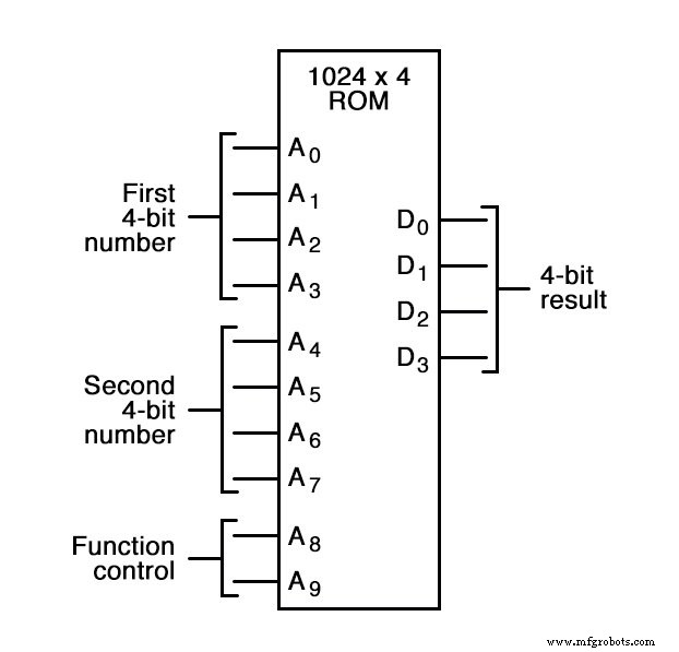
The power of look‑up tables grows with function complexity. For instance, a 4‑bit adder could be built using a ROM with 8 address lines (two 4‑bit operands) and 4 data lines for the signed sum. With 256 addressable locations, each input combination must be carefully programmed.
Programming such a table requires precision, but the benefit of software‑defined behavior outweighs the risk of a mis‑programmed entry.
Look‑up tables also excel in handling edge cases, such as overflow in 2’s complement addition. For example, adding 0111 (7) and 0110 (6) in a 4‑bit field yields 1001 (–7) instead of the correct 13. By programming the ROM to output a custom value—perhaps the maximum representable positive number—we can control the response to overflow conditions.
Beyond simple addition, expanding the ROM with two more address lines increases its capacity from 256 to 1,024 entries. This enables the ROM to perform multiple operations based on two control bits (A8 and A9): addition, subtraction (both orders), and equality testing—all on 4‑bit operands.
With even more address lines, the ROM can host a wide array of binary operations, such as parity checks or XORs, effectively acting as an Arithmetic Logic Unit (ALU). Historically, the IBM 1401 and 1620 computers employed look‑up tables for addition, a design choice that earned the nickname “CADET” (Can’t Add, Doesn’t Even Try).
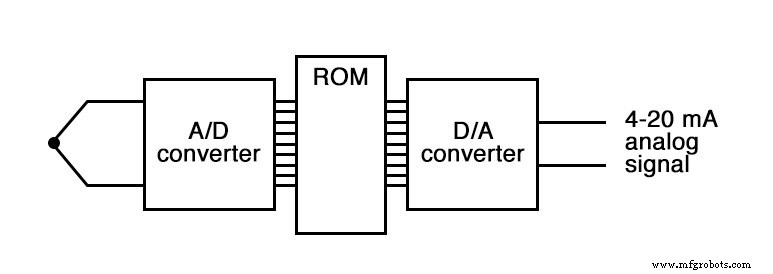
A common modern use of ROM‑based look‑up tables is in control systems that require a precise mathematical function. For example, automotive fuel‑injection systems adjust the air‑fuel ratio based on engine load, ambient temperature, and barometric pressure. Sensors measure these variables, their analog outputs are digitized, and the resulting digital vector serves as the ROM address. The ROM then outputs the optimal injection parameters.
ROMs also correct digitized signals. Thermocouple transmitters, for instance, convert a non‑linear millivoltage into a temperature value. By storing correction data in a ROM, the device can linearize the output, improving accuracy. This application is often referred to as a digital characterizer.
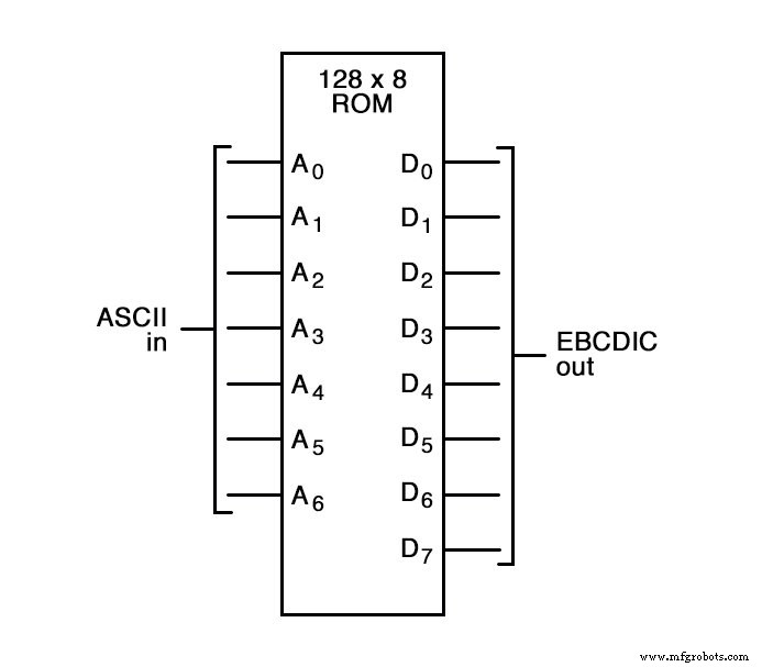
Another classic example is code translation. A 128 × 8 ROM can translate 7‑bit ASCII codes into 8‑bit EBCDIC codes by mapping each input to its corresponding output in the ROM table.
Related Worksheet: Memory Devices Worksheet
Industrial Technology
- How Lifting Tables Boost Workplace Ergonomics and Reduce Injury Risk
- Understanding Non‑Mechanical Digital Memories: SRAM, DRAM, and Flash
- Understanding ROM, PROM, EPROM, and EEPROM: Design, Programming, and Identification
- Microprocessors: The Evolution of Stored‑Program Computing
- Essential Guide to Choosing the Perfect Table for Your Home
- Pool Table – Design, History, and Construction Standards
- Dynamic Memory Allocation in C: Mastering malloc, calloc, realloc, and free
- Memory Technologies Powering Edge AI: Challenges and Opportunities
- Dynamic Memory Management in C: calloc, malloc, and free Explained
- Mastering C++ Dynamic Memory: Stack vs. Heap Explained