


From Truth Tables to Reliable Logic: Mastering Boolean Expressions for Safe Digital Design
When engineers design digital systems, they typically start with a truth table that outlines the desired logical behavior.
The challenge lies in selecting the appropriate circuitry—whether logic gates, relay assemblies, or programmable controllers—that faithfully implements that behavior.
While seasoned designers may instantly map a truth table to a hardware solution, systematic techniques exist for all engineers to follow.
Boolean algebra provides a clear, step‑by‑step method that transforms any truth table into a functional circuit.
To illustrate this process, let’s consider a realistic engineering problem: designing a flame‑detection system for a toxic‑waste incinerator.
High‑temperature combustion is used to neutralize hazardous waste. This method is common for medical waste that may carry deadly pathogens.
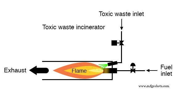
As long as a flame persists in the incinerator, it is safe to inject waste for destruction. If the flame extinguishes, any remaining waste could exit the exhaust unneutralized, posing a serious health risk.
Our system therefore requires a fool‑proof flame detector that allows waste injection only when a flame is verified.
Flame detection can be achieved through optical, thermal, or electrical‑conduction sensors—each with its own strengths and weaknesses.
Given the high hazard, the design calls for redundant detection: multiple sensors so that a single failure cannot trigger unsafe operation.
Each sensor supplies a normally‑open contact that closes when flame is detected. These contacts feed the logic system’s inputs.
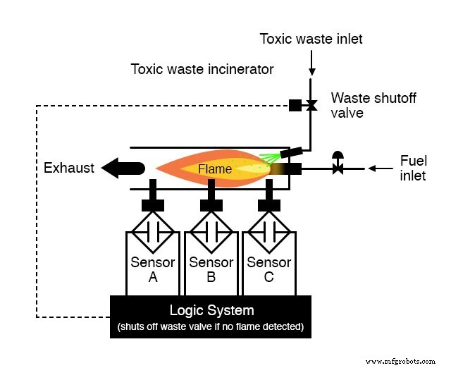
Our goal is to build logic that opens the waste valve only when the sensors confirm a flame.
First, we must define the logical behavior. Would a single sensor suffice? No—allowing the valve to open if just one out of three sensors reports flame defeats redundancy and safety.
Instead, we require all three sensors to agree before the valve opens. This approach guarantees that a single false “flame” reading cannot keep the valve open; all three would need to fail simultaneously—a highly unlikely scenario.
Consequently, the truth table is simple: the output is high only when inputs A, B, and C are all high.
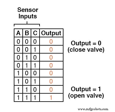
This function is readily achieved with a three‑input AND gate, which outputs high only when all inputs are high.

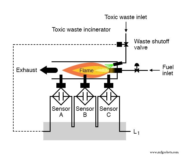
If relays are used, the AND behavior can be replicated by wiring the sensor contacts in series or by series‑wired relay contacts—only then will power reach the valve when every sensor confirms flame.
While this design maximizes safety, it also makes the system vulnerable to “flame‑false‑negative” failures: a sensor that fails to detect an actual flame will shut the valve unnecessarily, wasting fuel and downtime.
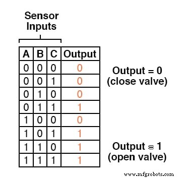
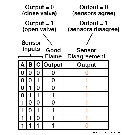
Ideally, we want a logic system that tolerates one false‑negative sensor but still protects against false‑positive errors. A “two‑out‑of‑three” rule satisfies both needs: the valve opens if at least two sensors report flame.
Below is the truth table for that logic.
Using Sum‑Of‑Products
At first glance, it’s not obvious which circuit will implement this truth table. The Sum‑Of‑Products (SOP) form of Boolean expression resolves that.
An SOP expression is a sum of product terms—each product being a conjunction of variables or their complements.
For example: ABC + BC + DF is a simple SOP where “ABC,” “BC,” and “DF” are the product terms.
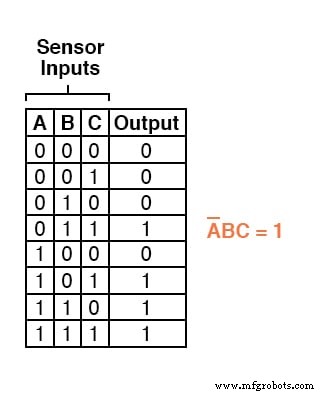
To generate an SOP from a truth table, list every row where the output is high (1) and write a product term that equals 1 for those inputs.
Consider the row where A=0, B=1, C=1. The product term is A′BC, which evaluates to 1 only under that exact condition.
The remaining high rows yield three more product terms:
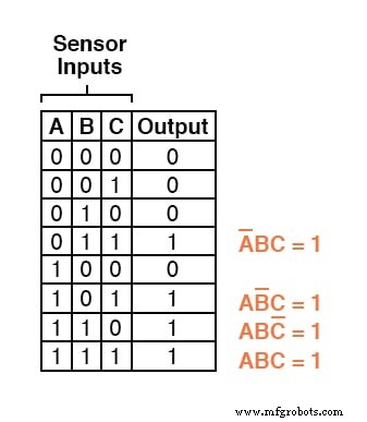
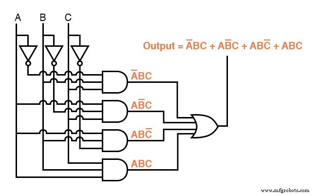
Combining them with logical OR gives the full SOP expression for the two‑out‑of‑three logic:
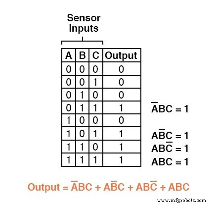
Once we have the SOP, designing the circuit is straightforward: each product term maps to an AND gate, and the OR of those gates produces the final output.
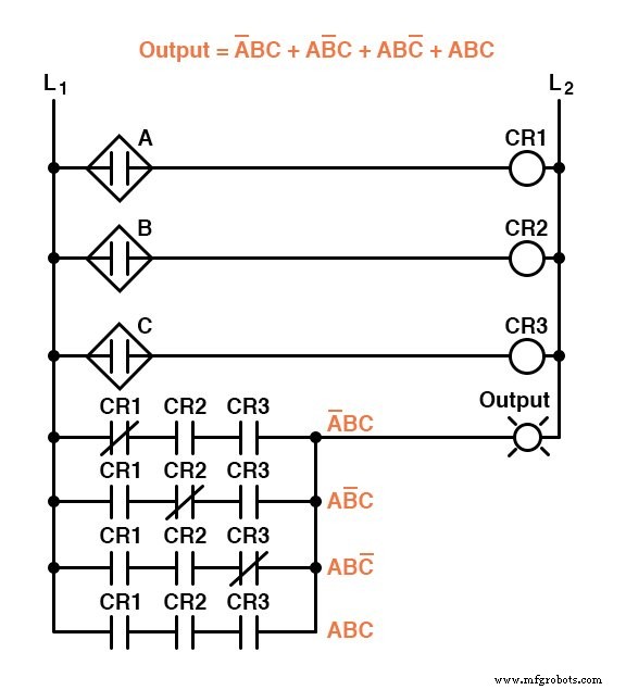
Although correct, these circuits can be bulky. Boolean algebra allows us to simplify the expression dramatically.
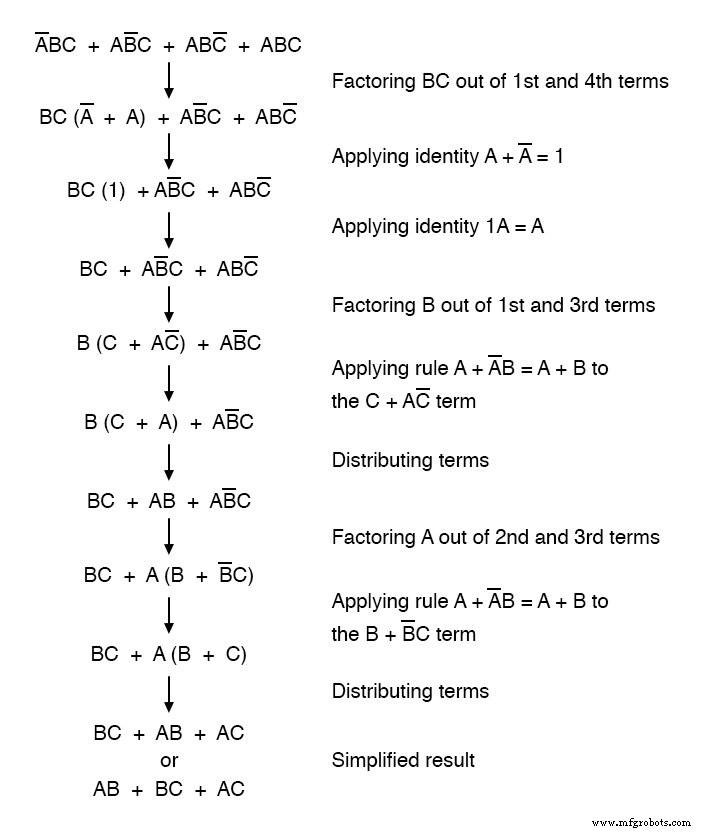
With the simplified expression, we can construct leaner logic—either with gates or relays—while preserving the same function.
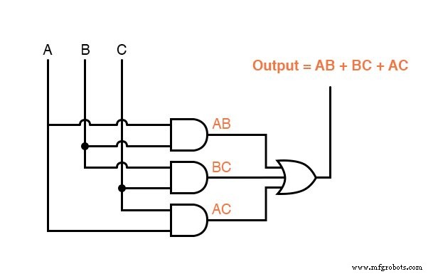
Either of these streamlined circuits will reliably control the incinerator’s waste valve based on a two‑out‑of‑three flame confirmation.
We can further enhance safety by adding logic that detects sensor disagreement—any condition where the three inputs are not identical.
When all sensors are functioning correctly, they should either all read low (000) or all read high (111). Any other combination (001, 010, 011, 100, 101, or 110) indicates a mismatch and potential failure.
An alarm triggered by such disagreement allows operators to assess whether to continue operation or shut down for safety.
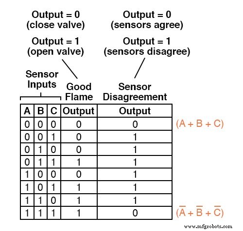
To design this “sensor‑disagreement” detector, we expand the truth table with an extra output column representing the alarm signal.
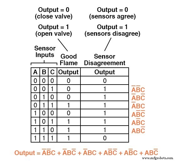
Generating an SOP for this column would involve six product terms—unwieldy and error‑prone.
Using Product‑Of‑Sums
Instead of summing the high rows, we can build a Product‑Of‑Sums (POS) expression that captures the low rows, resulting in fewer terms.
A POS expression multiplies sums of variables (OR terms) together. For example: (A + B)(C + D).
First, identify rows with a low (0) output and write a sum that evaluates to 0 under those input conditions.
For the first row (A=0, B=0, C=0), the sum term is (A + B + C), which equals 0 only when all three are zero.
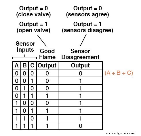
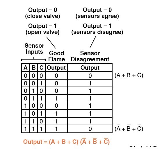
Only one other row produces a 0 output: A=1, B=1, C=1. The corresponding sum is (A′ + B′ + C′).
The complete POS expression is the product of these two sums:
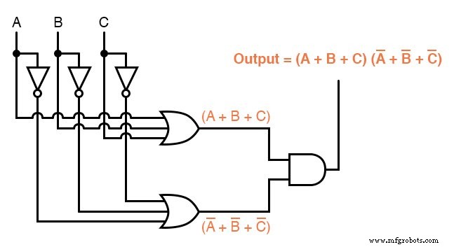
While an SOP maps naturally to a network of AND gates feeding a single OR gate, a POS maps to OR gates feeding a single AND gate.
Alternatively, the relay implementation of a POS uses parallel contacts in series, mirroring the gate configuration.
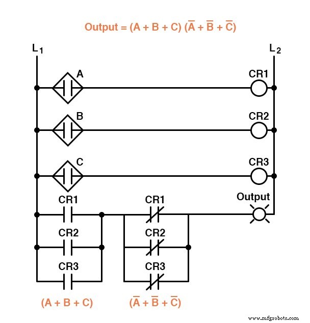
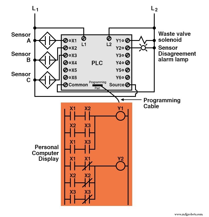
These two circuits illustrate the sensor‑disagreement logic alone; the full system combines the “good‑flame” and disagreement detectors.
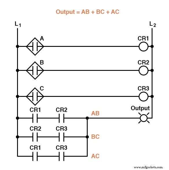
In a PLC implementation, the complete logic might look like this:
Both SOP and POS forms are powerful tools for deriving functional logic from a truth table. They enable deterministic, automatable design—so a computer could generate a custom logic circuit from a specification alone.
Because the conversion process is straightforward, it requires minimal creativity, allowing designers to focus on higher‑level safety and performance concerns.
REVIEW:
- Sum‑Of‑Products (SOP) expressions are built by listing rows with a high output, creating a product term for each, and summing them.
- SOP maps cleanly to a series of AND gates feeding a single OR gate.
- Product‑Of‑Sums (POS) expressions are built by listing rows with a low output, creating a sum term for each, and multiplying them.
- POS maps to a series of OR gates feeding a single AND gate.
RELATED WORKSHEETS:
- Sum‑of‑Products and Product‑of‑Sums Expressions Worksheet
- Boolean Algebra Worksheet
Industrial Technology
- Boolean Arithmetic: Adding, Multiplying, and Complementing in Digital Logic
- Mastering Karnaugh Maps: Simplify Logic with Truth Tables & Boolean Expressions
- Understanding Look‑Up Tables: From ROMs to Advanced ALUs
- Plasma vs. Flame Cutting Systems: Which is Right for Your Projects?
- Master Boolean Searches in E3.series: A Step‑by‑Step Guide
- Rewiring RichAuto DSP 0501 to A11E/S Controllers: A Step-by-Step Guide
- Agilent 8890 GC System – Precise Sulfur Analysis for Diesel & Residual Fuel Oils
- Enhancing Safety: Polyurethane Flame Resistance for Reliable Fire Protection
- The Definitive Guide to Logic Gate Truth Tables
- Exporting PLCnext Datalogger Data to CSV: A Step-by-Step Guide